
Electric vehicle charging station locking cable reel

a technology for electric vehicles and cable reels, which is applied in the direction of charging stations, transportation and packaging, and arrangement using take-up reels/drums, etc. it can solve the problems of high-risk theft targets, copper, and expensive metals, and achieve the effect of reducing the possibility of theft and prolonging the exposure to weather and sunligh

Active Publication Date: 2016-05-05
SCHNEIDER ELECTRIC USA INC
View PDF7 Cites 34 Cited by
  • Summary
  • Abstract
  • Description
  • Claims
  • Application Information

AI Technical Summary

Benefits of technology

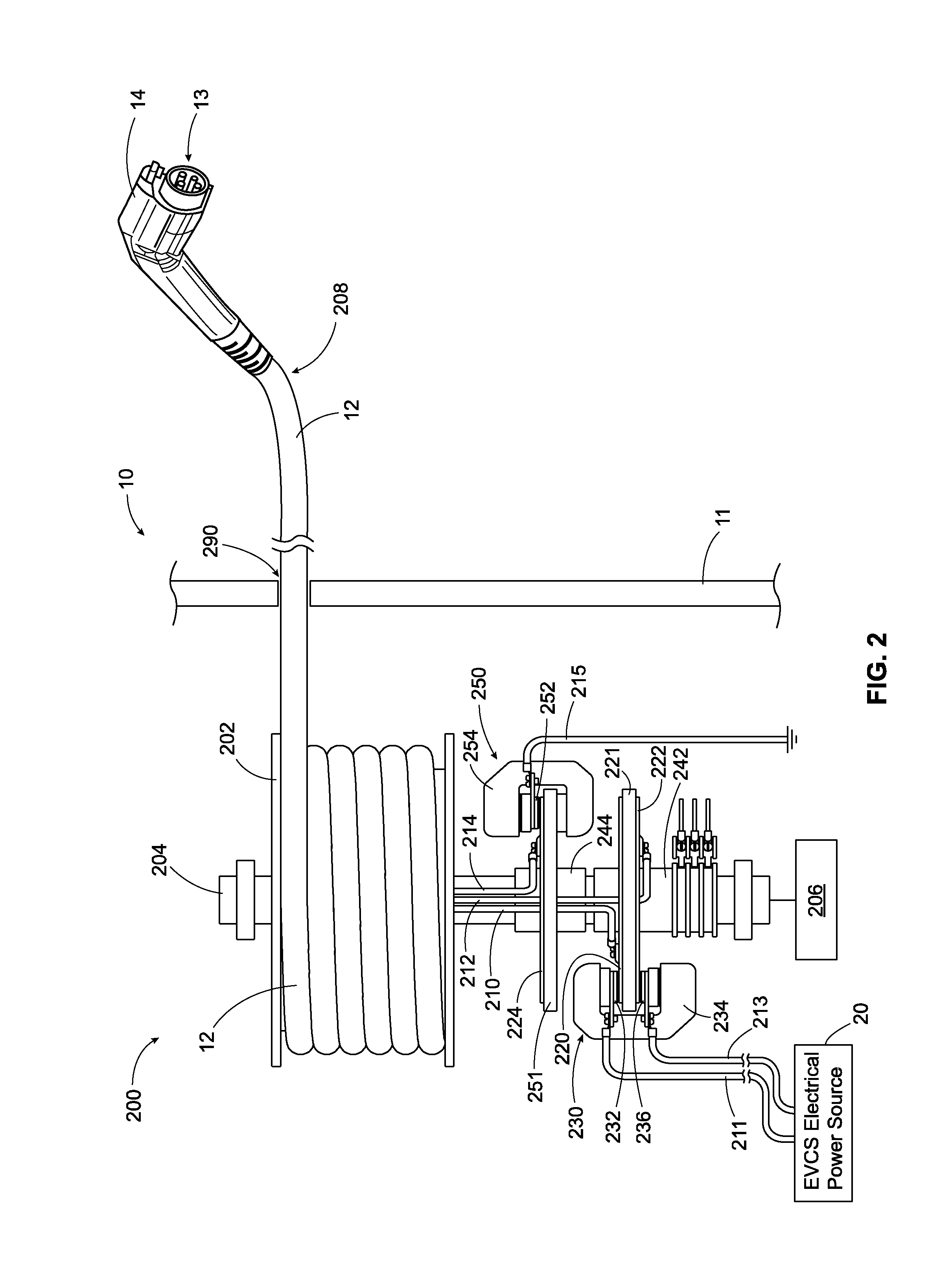
The patent describes a cable management system for an EVSE connector that allows the cable to be wound or unwound around a reel while keeping the data connections alive. The system uses data signals to control the locking or unlocking of the cable relative to the reel. The power conductors can run along the shaft or inside the hollow center of the shaft, and the calipers serve at least two functions—to electrically couple the power conductors and to mechanically stop or allow rotation of the reel and thereby lock the cable in a fixed position. The cable reel assembly may also take up any slack in the cable once retracted, preventing the cable from becoming twisted or a tripping hazard. The technical effects of this system include improved cable management and protection, as well as improved safety and reliability for EVSE charging.

Problems solved by technology

This long cable has several conductors made of copper, an expensive metal.
Thus, the exposed cable presents an apparent low risk, high-reward target for theft due to the significant copper content and lack of dangerous voltages.
In addition, in geographic locations that experience a harsh or unforgiving climate, prolonged exposure of the cable to the environment can lead to dielectric breakdown, cracking of the dielectric insulation material, and other deleterious effects that can pose a safety hazard to human operators.
Moreover, the long cable can become twisted or can pose a tripping hazard when it lies on the ground.

Method used


Image

  • Electric vehicle charging station locking cable reel
  • Electric vehicle charging station locking cable reel
  • Electric vehicle charging station locking cable reel

Examples


Embodiment Construction

[0014]Although the present disclosure will be described in connection with certain preferred embodiments, it will be understood that the present disclosure is not limited to those particular embodiments. On the contrary, the present disclosure is intended to cover all alternatives, modifications, and equivalent arrangements as may be included within the invention as defined by the appended claims.

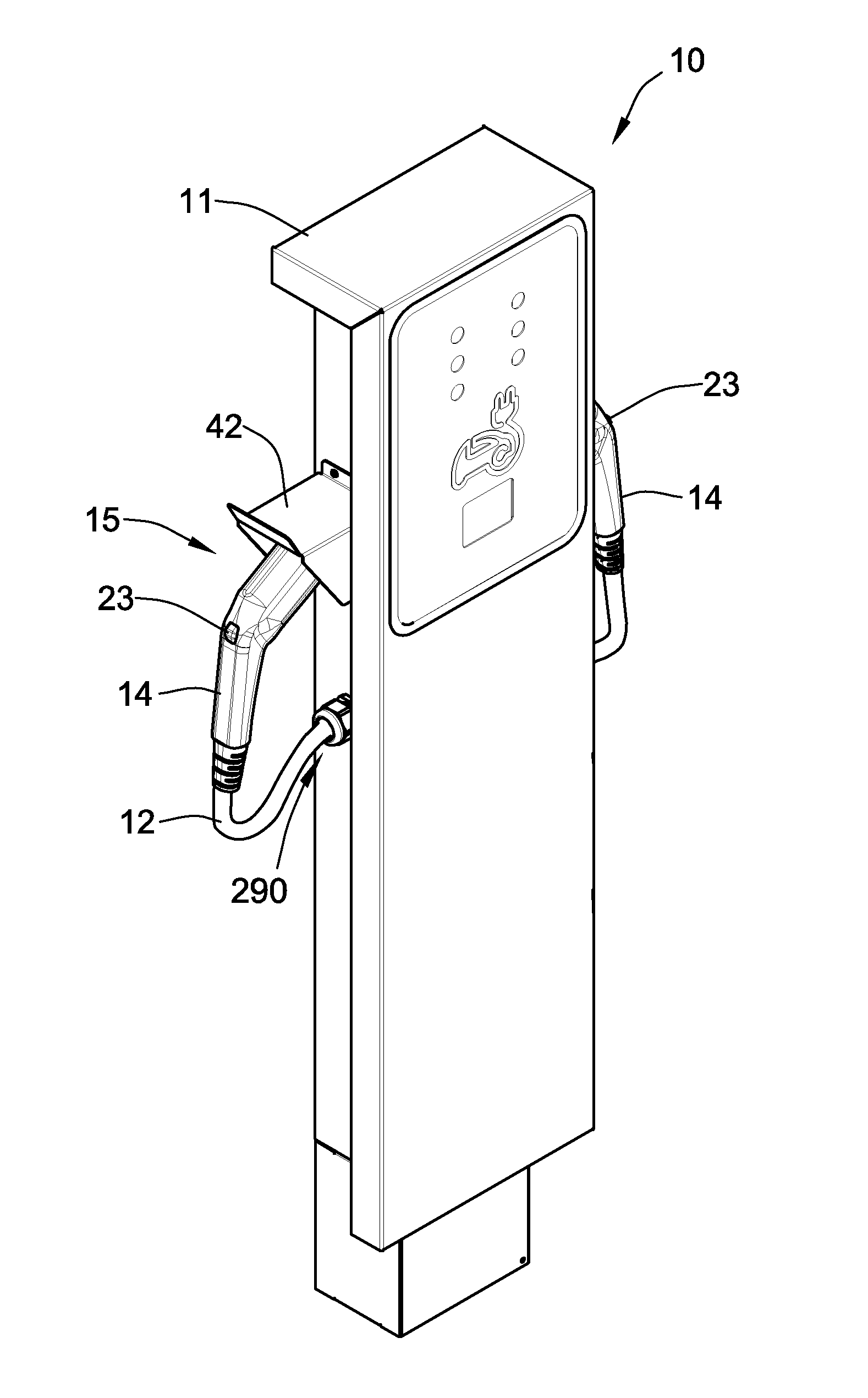
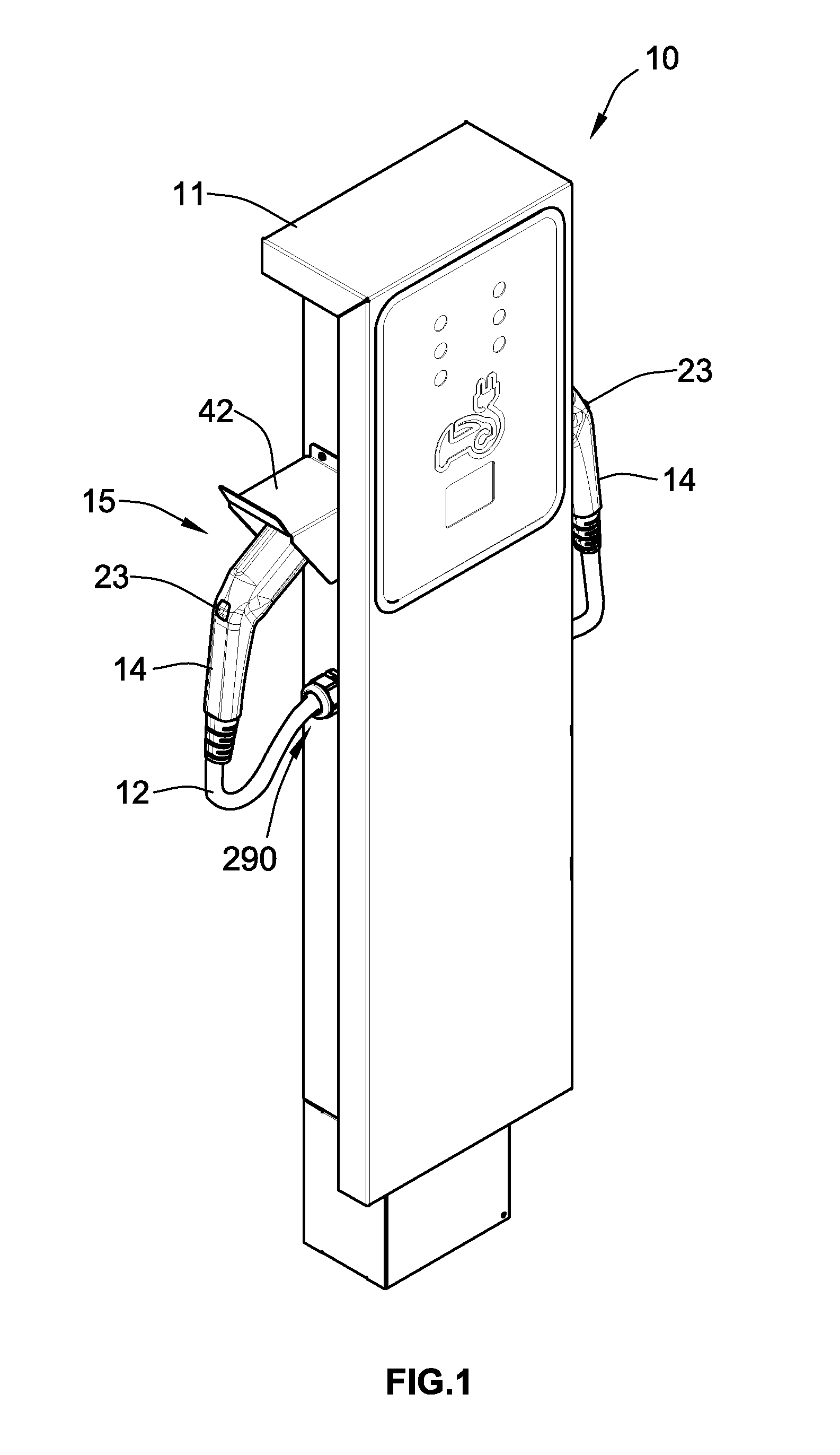
[0015]Turning now to the drawings, FIG. 1 illustrates an electric vehicle charging station (EVCS) or electric vehicle supply equipment (EVSE) 10 that includes a pedestal or housing 11 connected to an electrical power source 20 such as the local electric utility grid or a generator or a photovoltaic (PV) array, or any other source of electrical power, or any combination of the foregoing. In FIG. 1, the electrical power source 20 can refer to the connections from the EVCS 10 to the utility grid, generator, or PV array. Naturally, the utility grid, generator, or PV array itself would not be pa...


PUM


Abstract

A cable reel assembly in an electric vehicle supply equipment (EVSE) having a reel around which a cable is coiled. A shaft supporting the reel bears discs that rotate with the reel, and calipers coupled to the discs stop them and the reel from rotating. The power L1 and L2 conductors in the cable are electrically connected to the discs, and the calipers are electrically connected to the power source for the EVSE so that the calipers provide mechanical and electrical connection when actuated. Optionally, slip rings coupled to the shaft are connected to the control pilot and proximity signal conductors in the cable. Thus, during cable re traction, the control pilot and proximity signals are still provided to the EVSE, but the power conductors are decoupled from the power source. Only when the calipers are actuated to brake the discs is current flow permitted.

Description

FIELD OF THE DISCLOSURE[0001]The present disclosure relates generally to the charging of electric vehicles and, more particularly to the releasable locking of the power conductors in a cable used for the charging of electric vehicles.BACKGROUND OF THE DISCLOSURE[0002]An electric vehicle supply equipment (EVSE), also known as an electric vehicle charging station (EVCS), has a long cable terminated by a connector that plugs into the electric vehicle to charge its battery. This long cable has several conductors made of copper, an expensive metal. The cable is permanently attached to the charging station housing or pedestal, like a hose at a gas pump. In the United States, for example, the cable can be as long as 25 feet in length, as specified by the National Electrical Code (NEC), Article 625.[0003]For safety reasons, the cable is disconnected from the main power supply when the connector is not connected to an electric vehicle. Thus, the exposed cable presents an apparent low risk, h...

Claims


Application Information

Patent Timeline
Patent Type & Authority Applications(United States)
IPC IPC(8): B60L11/18
CPCB60L11/1816B60L11/1825H01H3/16H02G3/0493H02G11/02Y02T90/14B60L53/16B60L53/31B60L53/18Y02T10/70Y02T10/7072Y02T90/12
Inventor JEFFERIES, KEVIN M.EDWARDS, BENJAMIN W.WHITE, MATTHEW L.FILIPPENKO, KONSTANTIN A.WEILER, RICHARD K.
Owner SCHNEIDER ELECTRIC USA INC
Learn More