
Modular electric vehicle system

Active Publication Date: 2016-05-12
PRAIRIE MACHINE & PARTS MFG PARTNERSHIP
View PDF9 Cites 54 Cited by
  • Summary
  • Abstract
  • Description
  • Claims
  • Application Information

AI Technical Summary

Benefits of technology

The present invention is a modular electric vehicle that can be assembled from multiple interchangeable vehicle assembly modules. These modules offer flexibility in configurations and make it easy to disassemble and reassemble the vehicle for service or in applications with minimal routes of ingress. Each module has a central power bus and a central network bus that allows for easy interchangeability and repair. The modules can be either terminal or bidirectional, with a single central bus for control and communication with other modules. The vehicle assembly module can also have a powered axle for movement across a working surface and steering capabilities. The technical effects of this invention include maximized flexibility, simplified service, and improved user experience.

Problems solved by technology

One of the additional issues with the use of electric vehicles in industrial environments is the simplicity of repair.
One of the other limitations to date in the adoption of electric vehicles in mining and other industrial applications is that each time a vehicle was required with custom configuration or options it often required significant actual custom manufacture.
The variety of electric vehicles which were available for use in these types of applications was limited—a limited number of predetermined payloads or configurations would potentially be manufactured.
Purchasers desiring equipment of customized size or functionality were often left with either significant costs to manufacture on a custom basis or without the ability to procure a more fulsome menu of vehicle configurations.
Another limitation in terms of the size and flexibility of available configurations of electric vehicles which has potentially limited their commercial attraction to date, again particularly in industrial applications, is the size limitation.
Points of ingress to the working environment are limited in size such that vehicles have typically been limited to a smaller size so that they can be lowered into the working environment through such a shaft or opening.

Method used


Image

  • Modular electric vehicle system
  • Modular electric vehicle system
  • Modular electric vehicle system

Examples


Embodiment Construction

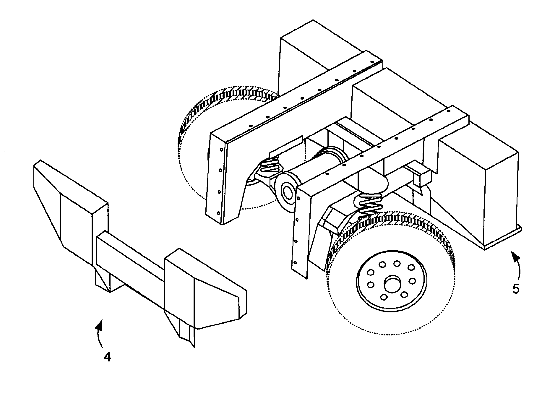
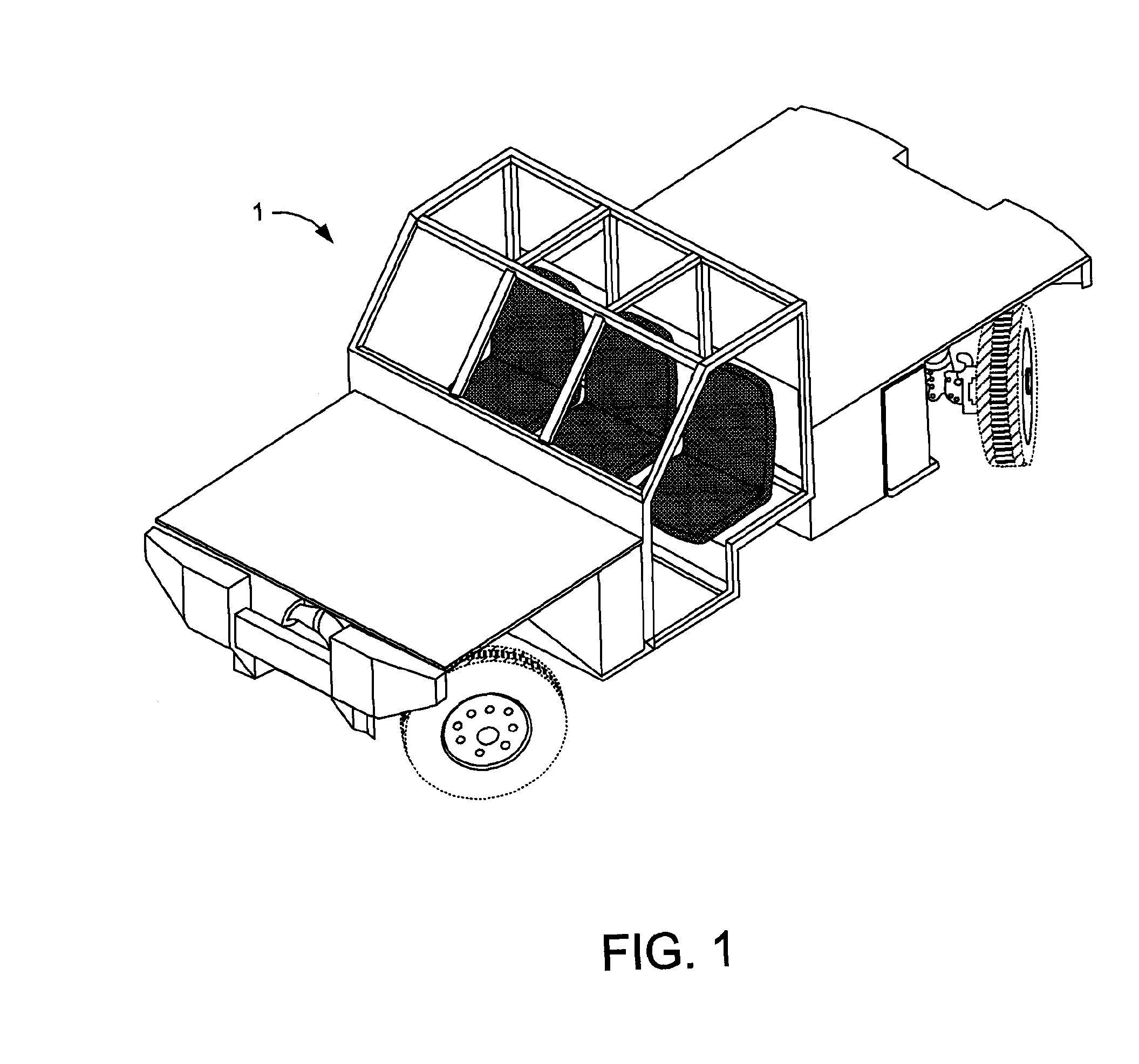
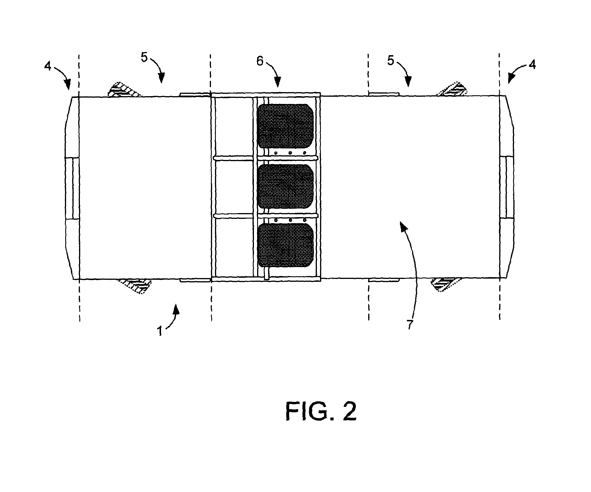
[0050]As outlined above, the overall concept of the present invention is a modular electric vehicle comprised of a plurality of discrete vehicle assembly modules. The combined integrated control system of the vehicle, comprised of a network of controllers on the modules connected by a central network bus, would be aware of the module configuration of the vehicle in total and would make available to the vehicle operator the appropriate control configuration to operate the vehicle in its assembled modular form.

Vehicle Requirements:

[0051]There are a number of basic concepts which are contemplated in the design of the modular electric vehicle of the present invention. It is desired to achieve a system where, either in factory or on site, a modular electric vehicle can be assembled from a plurality of interchangeable vehicle assembly modules.

[0052]In considering this approach in comparison to a pre-existing vehicle type, it can be thought of as dividing the prior art vehicle into a plura...


PUM


Abstract

A modular electric vehicle system, allowing for the assembly of many different vehicle configurations using a plurality of interchangeable vehicle assembly modules, including at least two powered vehicle assembly modules in an assembled vehicle each of which has self-contained drive and power systems and controls which can be connected together by a central network bus on the vehicle. At least one of the powered vehicle assembly modules will be a steering module, with the necessary additional controls and components to steer the axle thereon and in turn steer the assembled vehicle. The connection of the network bus and the modules would be done in an interchangeable way so that different modules could be interchangeably placed in the assembled vehicle. Various steering systems, control methodologies and vehicle attachments are also disclosed.

Description

[0001]This invention is in the field of electric utility and service vehicles, and more specifically relates to a system of modular vehicle assembly components and modules which allows for the flexible assembly and maintenance of electric vehicles of different configurations using various modules with a standardized attachment method and central network bus.BACKGROUND[0002]Electric vehicles have many different consumer and commercial applications. These vehicles typically consist of an electric motor drive as well as a rechargeable battery system—the vehicle is operated using power stored within the batteries, and when the batteries require it they can be recharged. At a consumer level, society is seeing a proliferation of electric cars and other similar vehicles—many consumers are motivated to purchase or drive an electric vehicle as an environmental choice, to minimize vehicle emissions.[0003]In commercial applications, there are environmental as well as other factors which in cer...

Claims


Application Information

Patent Timeline
IPC IPC(8): B62D63/02B60L15/32B60L15/20B60L11/18
CPCB62D63/025B60L15/20B60L15/32B60L11/18B60L2200/36B60L2200/40B60L2220/42B60L2200/44B60L2270/40B60P3/42Y02P90/60B60L50/60Y02T10/64Y02T10/72B60L15/00B62D61/12B62D31/025B62D7/04B62D7/15B60L50/00Y02T90/16Y02T10/70
Inventor BYRNES, PATRICLOCKERBIE, MICHAEL
Owner PRAIRIE MACHINE & PARTS MFG PARTNERSHIP
Learn More