

Interferometer, spectrophotometer using interferometer and control method for interferometer
- Summary
- Abstract
- Description
- Claims
- Application Information
AI Technical Summary
Benefits of technology
Problems solved by technology
Method used
Image

Examples
Embodiment Construction
[0035]The following describes an embodiment of the present invention referring to the accompanying drawings.
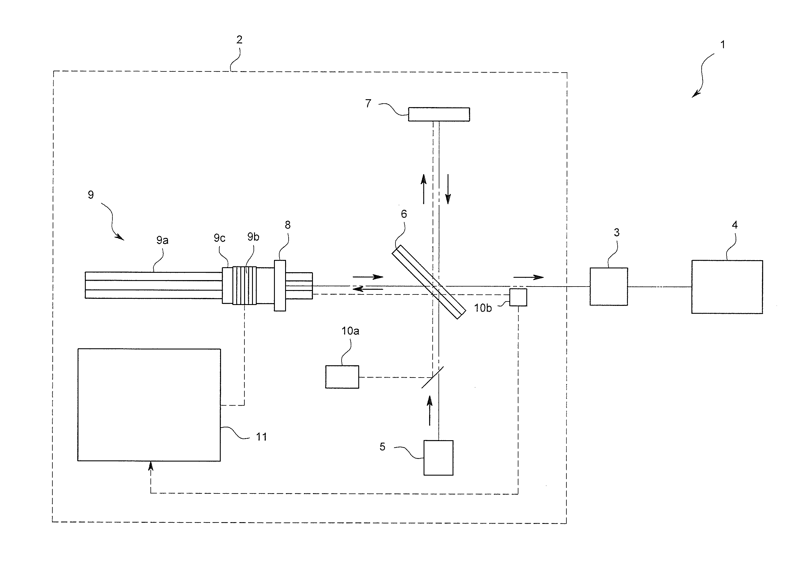
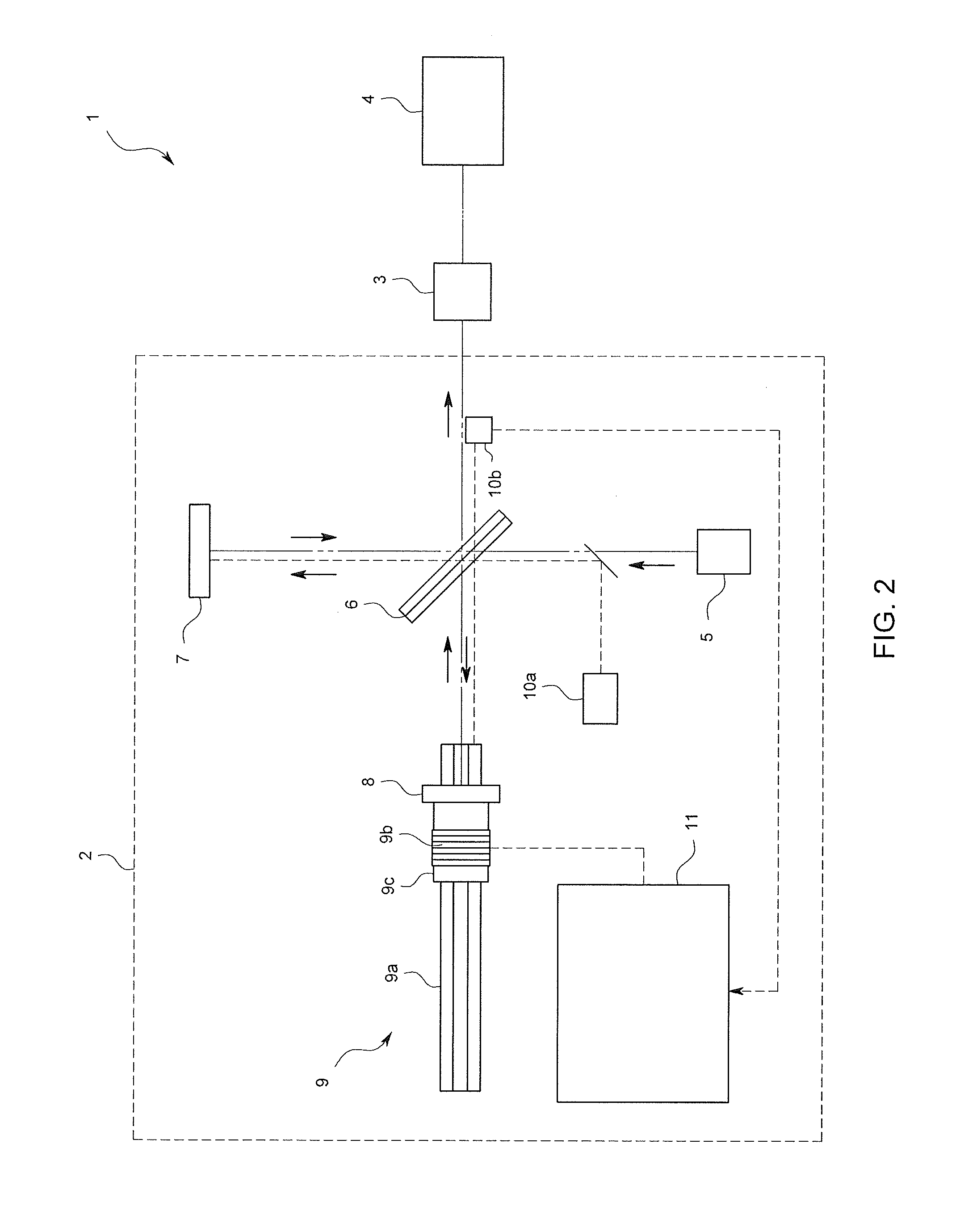
[0036]A spectrophotometer 1 of the present embodiment is, for example, a FTIR, and as shown in FIG. 2. An interference wave depicting different sine curves for each wavelength generated by an interferometer 2 is incident to a measurement sample placed on a sample stage 3. The light transmitted through the measurement sample is dispersed through Fast Fourier Transform (FFT) in an analyzing part 4 to thereby obtain the light intensity of every wavelength (spectrum). Thus, it is adapted to analyze a composition ratio and concentration of the measurement sample.
[0037]As a configuration of generating an interference wave depicting different sine curves for every wavelength, the interferometer 2 of the present embodiment splits light that emitted from an infrared light source 5 into two light beams through a beam splitter 6. Then, while one of the light beams is reflected by a fixed...
PUM
 Abstract
Description
Claims
Application Information