
Photoelectric conversion element and solar cell

Inactive Publication Date: 2016-05-12
FUJIFILM CORP
View PDF5 Cites 8 Cited by
  • Summary
  • Abstract
  • Description
  • Claims
  • Application Information

AI Technical Summary

Benefits of technology

The patent describes a new photoelectric conversion element and solar cell that use a compound with a perovskite crystal structure, which is a metal halide. The use of this compound improves the efficiency of the solar cell. The manufacturing process for the solar cell is simple, which means it can be made at a low cost. The technical benefits of this invention include a stable performance of the solar cell with low voltage fluctuation. A photoelectric conversion element and solar cell with this new compound can offer high performance and low cost manufacturing.

Problems solved by technology

However, when repeatedly manufacturing the above-described solar cell through the same manufacturing method using a compound having a perovskite crystal structure, there is a significant fluctuation in the voltage between the obtained solar cells (hereinafter, may be referred to as voltage fluctuation between solar cells), and thus stability of the cell performance is found to be insufficient.

Method used


Image

  • Photoelectric conversion element and solar cell
  • Photoelectric conversion element and solar cell
  • Photoelectric conversion element and solar cell

Examples


example 1

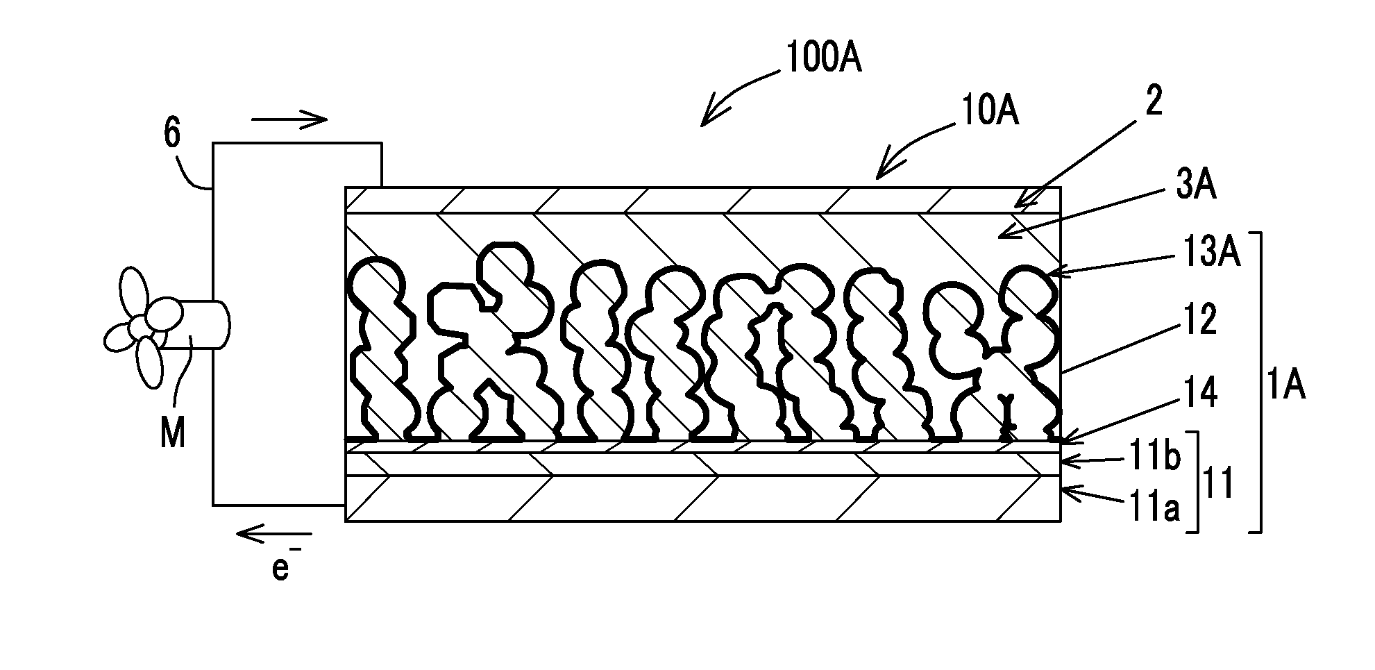
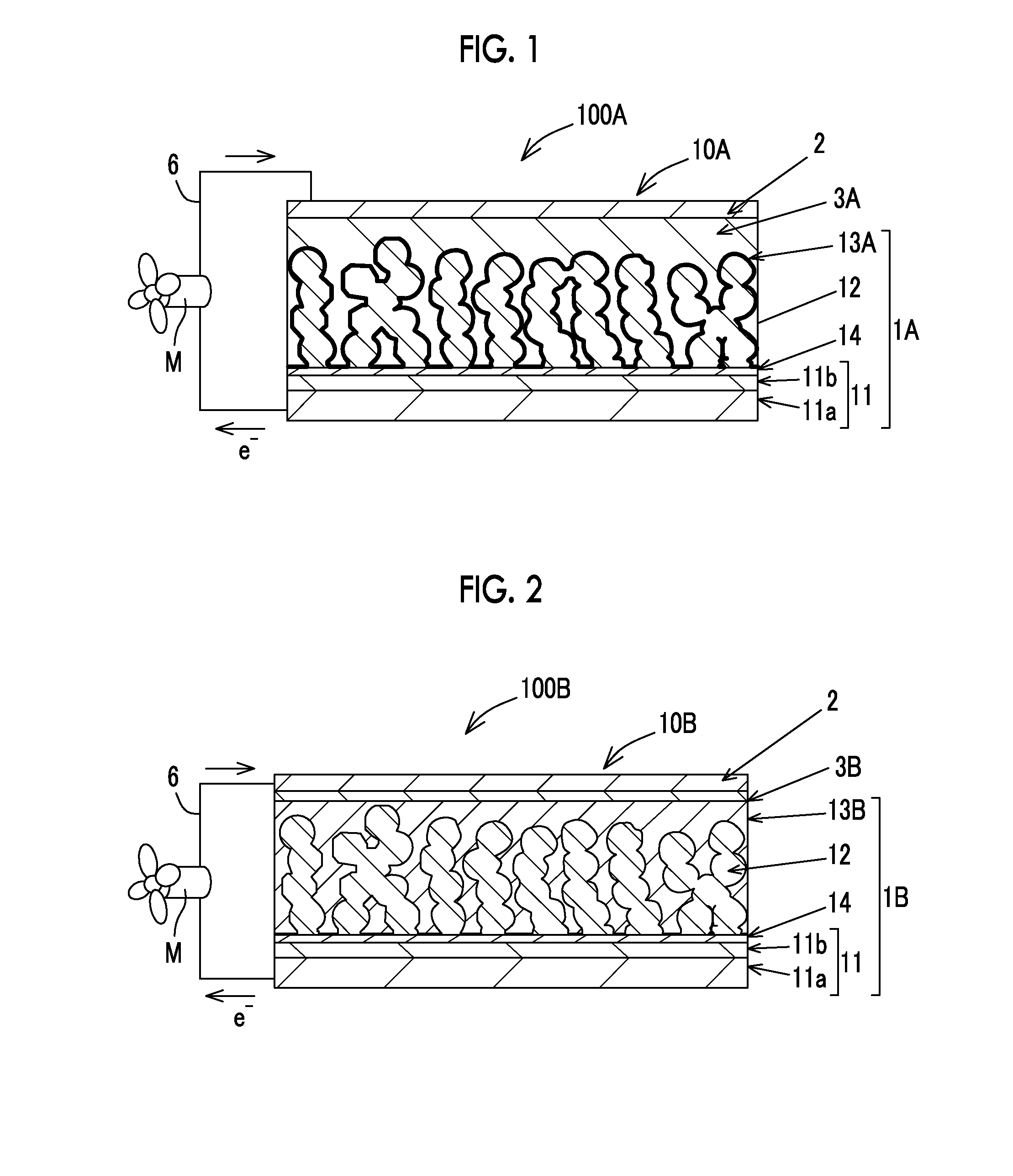
[0227]The photoelectric conversion element 10A and the solar cell shown in FIG. 1 were manufactured according to the following procedures. When the photosensitive layer 13 has a large thickness, the large thickness is provided to correspond to the photoelectric conversion element 10B and the solar cell shown in FIG. 2.

[0228]The porous material used in each example was used as an insulating material or a semiconductive porous material relative to the energy level of the lowest unoccupied molecular orbital (LUMO) of the perovskite compound.

[0229]The energy level (−3.9 eV) of the lowest unoccupied molecular orbital (LUMO) of the perovskite compound (CH3NH3PbI3) was calculated using the method described in Nanoscale Research Letters, 2012, 7: 353. The energy levels of LUMOs of the perovskite compounds calculated in the same manner are as follows: CH3NH3PbBr3 (−3.4 eV), [CH(═NH)NH3]PbI3 (−4.0 eV), and (CH3CH2NH3)2PbI4 (−3.4 eV).

[0230]The following energy levels of the porous materials we...


PUM


Abstract

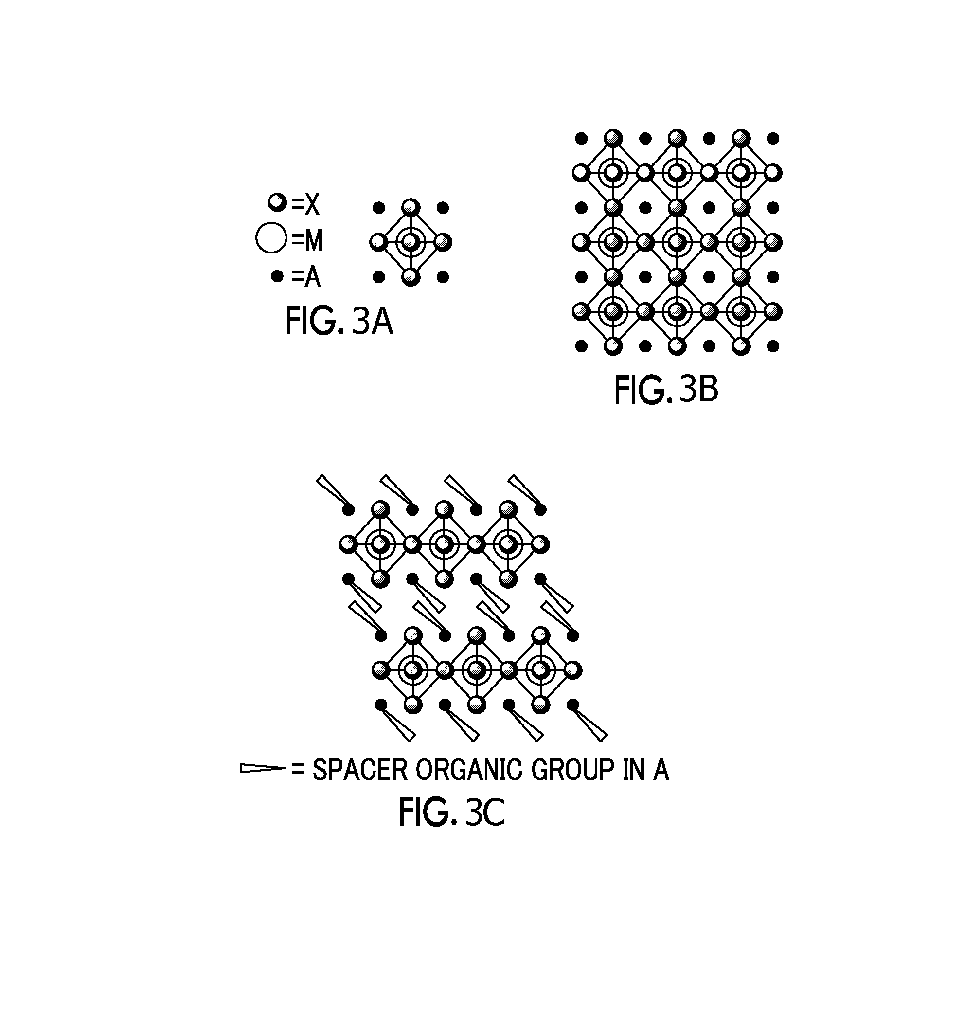
A photoelectric conversion element includes a first electrode which has a porous layer provided on a conductive support and a photosensitive layer having a light absorber on a surface of the porous layer, a second electrode which is opposed to the first electrode, and a solid hole transport layer which is provided between the first electrode and the second electrode. The light absorber includes a compound having a perovskite crystal structure having a cation of a group I element of the periodic table or a cation of a cationic organic group A, a cation of a metal atom M other than the group I elements of the periodic table, and an anion of an anionic atom X, and the porous layer contains at least one of insulating material. A solar cell includes this photoelectric conversion element.

Description

CROSS-REFERENCE TO RELATED APPLICATIONS[0001]This application is a Continuation of PCT International Application No. PCT / JP2014 / 069442 filed on Jul. 23, 2014, which claims priority under 35 U.S.C §119(a) to Japanese Patent Application No. 2013-159474 filed on Jul. 31, 2013 and Japanese Patent Application No. 2014-140942 filed on Jul. 8, 2014. Each of the above application(s) is hereby expressly incorporated by reference, in its entirety, into the present application.BACKGROUND OF THE INVENTION[0002]1. Field of the Invention[0003]The present invention relates to a photoelectric conversion element and a solar cell.[0004]2. Description of the Related Art[0005]Photoelectric conversion elements are used in various optical sensors, copiers, solar cells, and the like. Solar cells use inexhaustible solar energy and are expected to be put into real practical use. Among these, dye-sensitized solar cells using an organic dye, a Ru bipyridyl complex, or the like as a sensitizer are actively stu...

Claims


Application Information

Patent Timeline
IPC IPC(8): H01G9/20
CPCH01G9/2009H01G9/204H01G9/2031H01G9/2027Y02E10/549Y02E10/542H10K85/00H10K30/15H10K30/151H10K85/50
Inventor SATO, HIROTAKAKOBAYASHI, KATSUMI
Owner FUJIFILM CORP
Learn More