
Energy consumption brakingbraking device and method for servo driver

A technology of servo drive and energy-consumption braking, applied in the direction of stopping devices, etc., can solve the problems of reducing the service life and work performance of the servo drive, torque ripple, etc., to improve stability and work performance, stabilize the bus voltage, improve The effect of work performance

Active Publication Date: 2012-12-19
湖北立锐机电有限公司
View PDF6 Cites 9 Cited by
  • Summary
  • Abstract
  • Description
  • Claims
  • Application Information

AI Technical Summary

Problems solved by technology

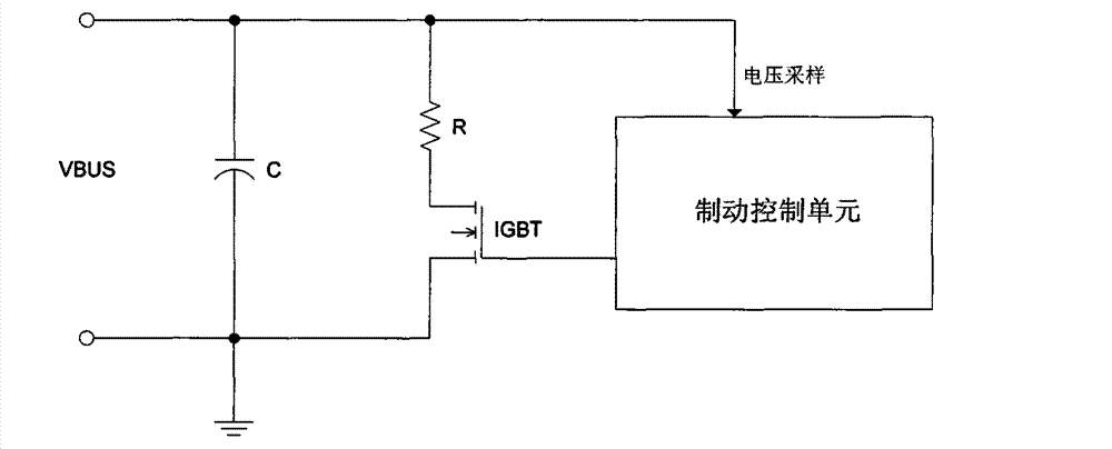
However, since this control method detects that the bus voltage reaches the upper threshold or lower threshold, it will act, and adopts hysteresis control, so that the bus voltage will fluctuate between the set upper and lower thresholds during the braking process.
The fluctuation of the bus voltage undoubtedly affects the life of the capacitor C on the bus, and also causes torque ripple, which reduces the service life and working performance of the servo drive

Method used


Image

  • Energy consumption brakingbraking device and method for servo driver
  • Energy consumption brakingbraking device and method for servo driver
  • Energy consumption brakingbraking device and method for servo driver

Examples


Embodiment Construction

[0039] In order to make it easier for those skilled in the art to understand and implement the present invention, the present invention will be further described in detail below in conjunction with the accompanying drawings and specific embodiments.

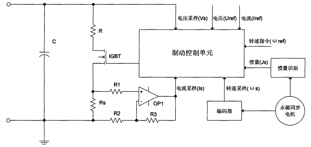
[0040] The circuit block diagram of energy consumption braking unit of the present invention is as figure 2As shown, the current sampling, speed output and inertia identification modules are added to the traditional dynamic braking unit, where the speed output includes the operating speed ωs and the given speed ωref, and the corresponding control algorithm is pre-calculated to obtain a feedback energy value At the same time, during the speed change process, the vector control adjustment module is sampled in real time and the Iref and Uref of each unit time interval are calculated. From Iref and Uref, another value ΔW2 of the feedback energy can also be calculated, and the feedback energy ΔW1 and After ΔW2 is weighted, the feedba...


PUM


Abstract

The invention relates to an energy consumption brakingbraking device and method for the servo driver. The energy consumption braking device comprises a current sampling module, a rotation speed outputting module, an inertia identifying module and a braking controlling unit; the current sampling module is used for detecting the current signal Ir flowing through the braking resistor R and outputting the current signal to the braking controlling unit; the rotation speed outputting module is used for outputting the running rotation speed (omega)s and the given rotation speed (omega)ref of the servo motor; the inertia identifying module is used for obtaining the current rotating inertia Js of the servo motor; the braking controlling unit pre-calculates according to the control algorithm to obtain the feedback energy (delta)W, and calculates the braking energy consumption (delta)Wf in real time according to the current signal Ir flowing through the braking resistor in the braking process, and makes the feedback energy (delta) W be equal to the braking energy (delta)Wf through the feedback controlling link, so as to realize the energy consumption braking process.

Description

technical field [0001] The present invention relates to a braking device, in particular to a dynamic braking device for a servo driver, and a method for dynamic braking for a servo driver, which is based on the predicted Energy is used to plan the braking process of the motor in advance, and relevant information is collected in real time during the braking process to adjust the braking control amount, so that the fluctuation of the bus voltage is controlled within a small range, and the torque fluctuation of the system is suppressed. Background technique [0002] The energy fed back by the motor during the braking process of the servo drive will increase the bus voltage, and the amplitude of the bus voltage increase ΔU=(2×ΔW / C)^0.5, where ΔW is the feedback energy, and C is connected in parallel on the bus Capacitance value. At this time, if the energy consumption braking unit is not added to absorb the feedback energy, the bus voltage rise too high will break down the capa...

Claims


Application Information

Patent Timeline
IPC IPC(8): H02P6/24
Inventor 苏智胜
Owner 湖北立锐机电有限公司
Learn More