Photoelectric conversion element, solar cell, and method for manufacturing photoelectric conversion element

Inactive Publication Date: 2017-09-07
FUJIFILM CORP
View PDF4 Cites 2 Cited by
  • Summary
  • Abstract
  • Description
  • Claims
  • Application Information

AI Technical Summary

Benefits of technology

[0012]An object of the present invention is to provide a photoelectric conversion element which has a photoelectric conversion efficiency that does not significantly fluctuate, is capable of exhibiting stable cell performance, and, furthermore, has excellent moisture resistance and high-humidity light resistance and a solar cell for which the photoelectric conversion element is used. In addition, another object of the present invention is to provide a method for manufacturing a photoelectric conversion element which has a photoelectric conversion efficiency that does not significantly fluctuate, is capable of exhibiting stable cell performance, and, furthermore, has excellent moisture resistance and high-humidity light resistance.
[0013]In the manufacturing of photoel

Problems solved by technology

However, these photoelectric conversion elements and solar cells have been attracting attention in recent years, but there is no sufficient amount of knowledge about cell performance other than photoelectric conversion efficiencies.
As a result of repetitively manufacturing the solar cells using a perovskite compound of a metal halide or the like and the same manufacturing method in the above-described circumstances, it was found that there is a huge variation in photoelectric conversion efficiencies among the obtained solar cells and the stability of cell performance is not sufficien

Method used


Image

  • Photoelectric conversion element, solar cell, and method for manufacturing photoelectric conversion element
  • Photoelectric conversion element, solar cell, and method for manufacturing photoelectric conversion element
  • Photoelectric conversion element, solar cell, and method for manufacturing photoelectric conversion element

Examples


example 1

[0261](Manufacturing of Photoelectric Conversion Element (Specimen No. 101))

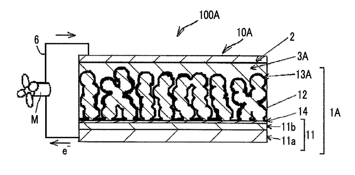
[0262]The photoelectric conversion element 10A illustrated in FIG. 1 were manufactured in an order described below.

[0263]11>

[0264]A fluorine-doped SnO2 conductive film (the transparent electrode 11b, film thickness: 0.3 μm) was formed on a glass substrate (the support 11a, thickness: 2.2 mm, 25 mm×25 mm), thereby producing a conductive support 11.

[0265]

[0266]An isopropanol solution containing 15% by mass of titanium diisopropoxide bis(acetylacetonate) (manufactured by Sigma-Aldrich Japan K.K.) was diluted with 1-butanol, thereby preparing 0.02 M of a solution for a blocking layer.

[0267]14>

[0268]A blocking layer 14 made of titanium oxide (having a film thickness of 100 nm) was formed on the SnO2 conductive film using 0.02 M of the solution for the blocking layer at 450° C. by means of a spray thermal decomposition method.

[0269]

[0270]Ethyl cellulose, lauric acid, and terpineol were added to an ethanol dispersi...

example 2

[0326]Photoelectric conversion elements 10A were manufactured in the same manner as in the manufacturing of the photoelectric conversion element of Example 1 except for the fact that, in the manufacturing of the photoelectric conversion element of Example 1, a light absorber solution prepared by changing the molar ratio between CH3NH3I and PbI2 to 3:1 was used. The obtained perovskite compound included (CH3NH3)2PbI4. As a result of evaluating the obtained photoelectric conversion elements by means of Tests 1 to 3 in the same manner as in Example 1, all of the photoelectric conversion elements obtained excellent results in the same manner as the respective conversion elements of Specimen Nos. 101 to 127.

[0327]The present invention has been described together with embodiments thereof, but the present inventors do not limit the present invention in any detailed part of the description unless particularly otherwise described and consider that the present invention is supposed to be wide...


PUM


Abstract

A photoelectric conversion element including: a first electrode having a photosensitive layer including a light absorber on a conductive support; a second electrode facing the first electrode; and a hole transport layer provided between the first and the second electrodes, in which the light absorber includes a compound having a perovskite-type crystal structure having a cation of Group 1 element of the periodic table or a cationic organic group A, a cation of a metallic atom M that is not Group 1 element of the periodic table, and an anion of an anionic atom X, and an organic solvent content per cubic millimeter of the hole transport layer is 1×10⁻¹⁰ to 1×10⁻⁷ mol, a solar cell using this photoelectric conversion element, and a method for manufacturing a photoelectric conversion element including a step of applying a hole-transporting material solution and drying the solution at 40° C. to 180° C.

Description

CROSS-REFERENCE TO RELATED APPLICATIONS[0001]This application is a Continuation of PCT International Application No. PCT / JP2015 / 082559 filed on Nov. 19, 2015, which claims priority under 35 U.S.C. §119 (a) to Japanese Patent Application No. 2014-236632 filed on Nov. 21, 2014. Each of the above applications is hereby expressly incorporated by reference, in its entirety, into the present application.BACKGROUND OF THE INVENTION[0002]1. Field of the Invention[0003]The present invention relates to a photoelectric conversion element, a solar cell, and a method for manufacturing a photoelectric conversion element.[0004]2. Description of the Related Art[0005]Photoelectric conversion elements are used in a variety of optical sensors, copiers, solar cells, and the like. It is anticipated that solar cells will be actively put into practical use as cells using non-exhaustible solar enemy. Among them, active research and development is underway regarding dye sensitized solar cells in which an or...

Claims


Application Information

Patent Timeline
IPC IPC(8): H01G9/20H01L51/44H01L51/00H01L51/42
CPCH01G9/2018H01L51/4253H01L51/0056H01L51/0077H01L51/006H01L51/442Y02E10/549Y02E10/542Y02P70/50H10K71/15H10K71/311H10K85/00H10K85/633H10K85/30H10K30/151H10K2102/102H10K85/50H10K30/30H10K30/82H10K85/624
Inventor YAMAMOTO, YOSUKESATOU, HIROTAKAKOBAYASHI, KATSUMI
Owner FUJIFILM CORP
Why Eureka
Try Eureka