Photoelectric conversion element and solar cell

Inactive Publication Date: 2016-05-19
FUJIFILM CORP
View PDF3 Cites 5 Cited by
  • Summary
  • Abstract
  • Description
  • Claims
  • Application Information

AI Technical Summary

Benefits of technology

This patent is about a photoelectric conversion element and a solar cell that use a perovskite compound as a light absorber. The invention aims to reduce fluctuations in the efficiency of the conversion of light to electricity. By substituting certain metal atoms and using a specific cationic group, the inventors found that the stability of the conversion efficiency can be improved. This results in a photoelectric conversion element and solar cell with consistent and reliable performance. Manufacturing these cells through the same method can also produce cells with consistent efficiency. Overall, the invention provides a solution for improving the reliability and efficiency of solar cells.

Problems solved by technology

However, the photoelectric conversion element and the solar cell have attracted attention in recent years, and cell performance other than the photoelectric conversion efficiency is little known.
In such a state, when repeatedly manufacturing the above-described solar cell through the same manufacturing method using a compound having a perovskite crystal structure, that is a metal halide, the variation in the photoelectric conversion efficiency between the obtained solar cells is great, and thus stability of the cell performance is found to be insufficient.

Method used


Image

  • Photoelectric conversion element and solar cell
  • Photoelectric conversion element and solar cell
  • Photoelectric conversion element and solar cell

Examples


example 1

[0246]Solar cells were manufactured using a light absorber containing the above-described perovskite compound (P1), and the fluctuation in the photoelectric conversion efficiency was evaluated.

[0247](Manufacturing of Photoelectric Conversion Element and Solar Cell (Sample No. 101))

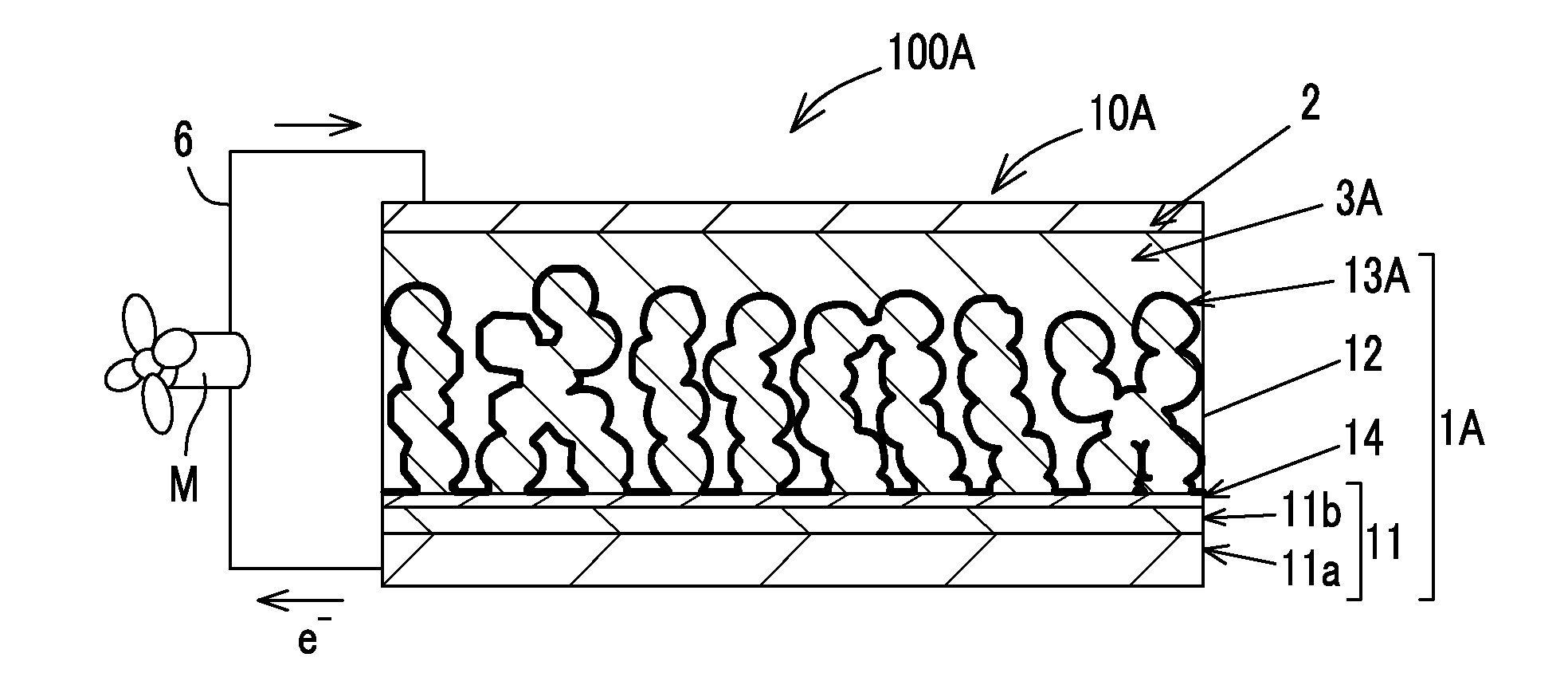
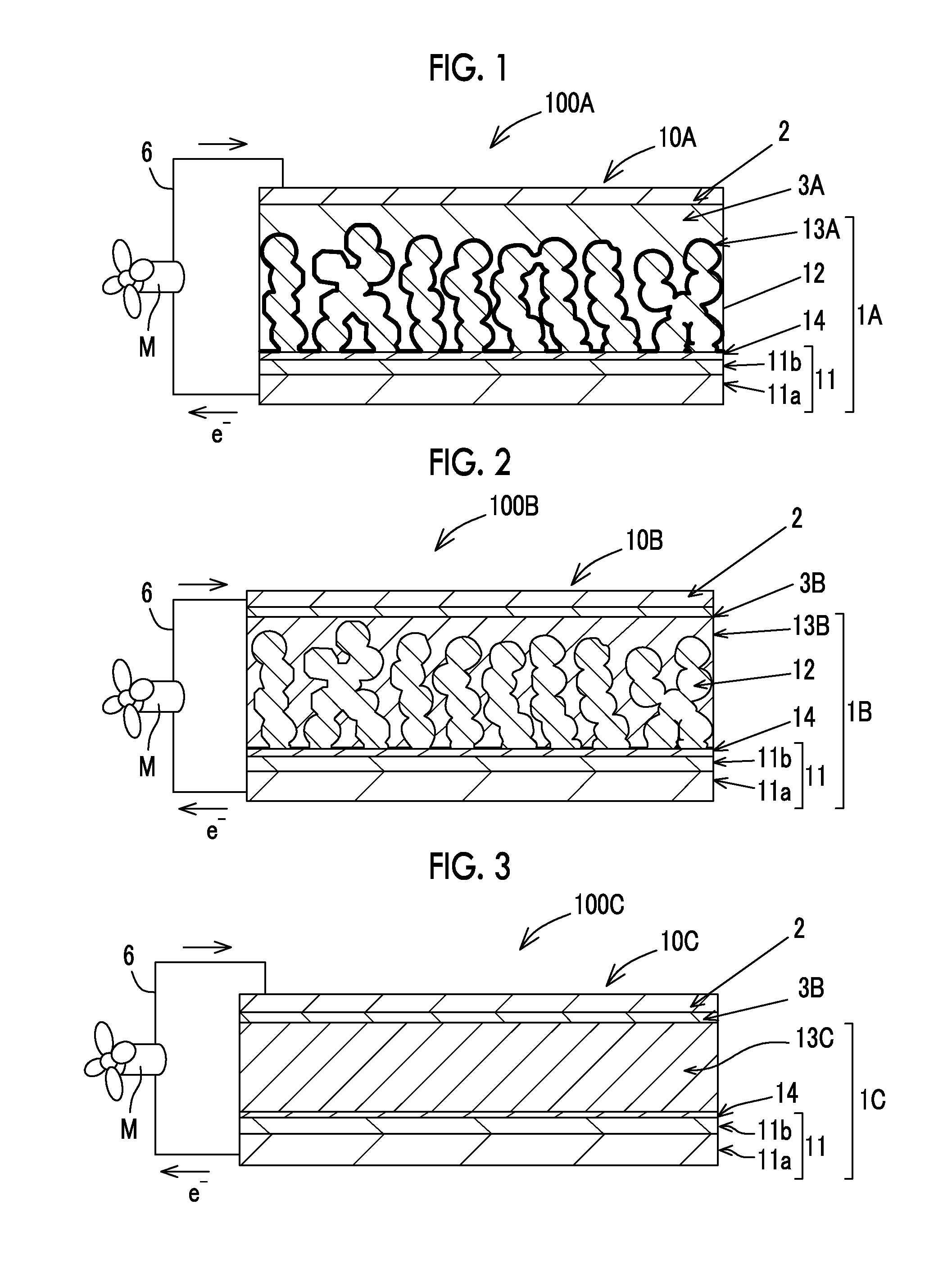
[0248]A photoelectric conversion element 10 and a solar cell of the invention were manufactured according to the following procedures.

[0249]14>

[0250]A 15 mass % isopropanol solution of titanium diisopropoxide bis(acetylacetonato) (manufactured by Sigma-Aldrich Co. LLC.) was diluted with 1-butanol to prepare a 0.02 M solution for a blocking layer.

[0251]A fluorine-doped, conductive SnO2 film (transparent electrode 11b) was formed on a glass substrate (support 11a, thickness: 2.2 mm) to produce a conductive support 11. Using the prepared 0.02 M solution for a blocking layer, a blocking layer 14 (thickness: 50 nm) was formed on the conductive SnO2 film at 450° C. through a spray pyrolysis method.

[0252]12>

[0253...

example 2

[0303]Solar cells were manufactured using a light absorber containing the above-described perovskite compound (P′), and the fluctuation in the photoelectric conversion efficiency was evaluated.

[0304](Manufacturing of Photoelectric Conversion Element and Solar Cell (Sample No. 201))

[0305]A photoelectric conversion element and a solar cell of the invention (Sample No. 201) were manufactured in the same manner as in the manufacturing of the photoelectric conversion element and the solar cell (Sample No. 101), except that in the manufacturing of the photoelectric conversion element and the solar cell (Sample No. 101), the following light absorber solution E was used in place of the light absorber solution A.

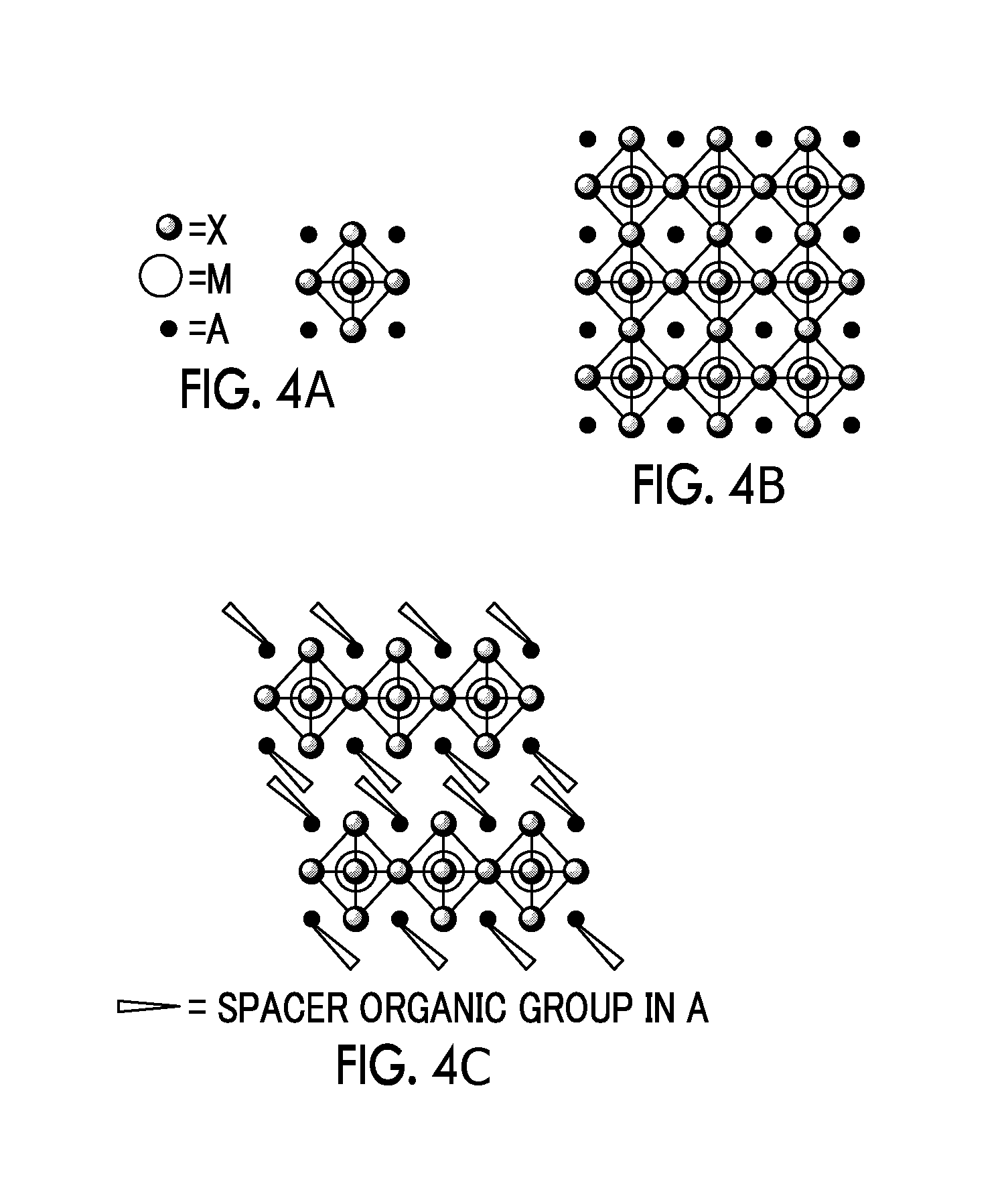
[0306]The photosensitive layer of the manufactured photoelectric conversion element and solar cell contained a perovskite compound (PB1) having a perovskite crystal structure with CH3CH2—NH3+ as a cation A1, (Pb2+0.99Sn2+0.01) as a metal cation, and I− as an anion X and represented b...

example 3

[0319]Solar cells were manufactured using a light absorber containing the above-described perovskite compound (P2), and the fluctuation in the photoelectric conversion efficiency was evaluated.

[0320](Manufacturing of Photoelectric Conversion Element and Solar Cell (Sample No. 301))

[0321]A photoelectric conversion element and a solar cell of the invention (Sample No. 301) were manufactured in the same manner as in the manufacturing of the photoelectric conversion element and the solar cell (Sample No. 101), except that in the manufacturing of the photoelectric conversion element and the solar cell (Sample No. 101), the following light absorber solution F was used in place of the light absorber solution A.

[0322]The photosensitive layer of the photoelectric conversion element and the solar cell contained a compound (PB2) having a perovskite crystal structure represented by (CF3CH2—NH3)2PbI4 with CF3CH2—NH3+ as a cation A2, Pb2+ as a metal cation, and I− as an anion X.

[0323]

[0324]The li...


PUM


Abstract

A photoelectric conversion element includes a first electrode which has a photosensitive layer containing a light absorber on a conductive support, a second electrode which is opposed to the first electrode, and a hole transport layer which is provided between the first electrode and the second electrode, and the light absorber contains at least one of compound (P) having a perovskite crystal structure represented by the following Formula (I). A solar cell includes this photoelectric conversion element.Aa(MA1(1-n)MA2n)mAXx  Formula (I):

Description

CROSS-REFERENCE TO RELATED APPLICATIONS[0001]This application is a Continuation of PCT International Application No. PCT / JP2014 / 069464 filed on Jul. 23, 2014, which claims priority under 35 U.S.C §119(a) to Japanese Patent Application No. 2013-159473 filed on Jul. 31, 2013 and Japanese Patent Application No. 2014-140941 filed on Jul. 8, 2014. Each of the above application(s) is hereby expressly incorporated by reference, in its entirety, into the present application.BACKGROUND OF THE INVENTION[0002]1. Field of the Invention[0003]The present invention relates to a photoelectric conversion element and a solar cell.[0004]2. Description of the Related Art[0005]Photoelectric conversion elements are used in various optical sensors, copiers, solar cells, and the like. Solar cells use inexhaustible solar energy and are expected to be put into real practical use. Among these, dye-sensitized solar cells using an organic dye, a Ru bipyridyl complex, or the like as a sensitizer are actively stu...

Claims


Application Information

Patent Timeline
IPC IPC(8): H01G9/20
CPCH01G9/2004Y02E10/549Y02E10/542Y02P70/50H10K85/00H10K30/151H10K85/50
Inventor SATO, HIROTAKAKOBAYASHI, KATSUMI
Owner FUJIFILM CORP
Why Eureka
Try Eureka