Multiple template improved 3D modeling of imaged objects using camera position and pose to obtain accuracy

a technology of imaged objects and camera positions, applied in the field of optical systems, can solve the problems of not providing a way to get a 3d model of the scene, affecting the use of consumer devices with limited processing power, and affecting the use of optical devices

Inactive Publication Date: 2016-05-12
JOVANOVIC DEJAN +3
View PDF17 Cites 63 Cited by
  • Summary
  • Abstract
  • Description
  • Claims
  • Application Information

AI Technical Summary

Problems solved by technology

The scene typically contains 3D objects in a 3D environment but much of the 3D structure, such as size and shape of the objects or distance between objects, is lost in the 2D photographic view.
The photo does not provide ...

Method used


Image

  • Multiple template improved 3D modeling of imaged objects using camera position and pose to obtain accuracy
  • Multiple template improved 3D modeling of imaged objects using camera position and pose to obtain accuracy
  • Multiple template improved 3D modeling of imaged objects using camera position and pose to obtain accuracy

Examples


first embodiment

[0068]Light pattern projector 230. One embodiment of this invention uses a visible laser similar to those used in laser pointers followed by an optical element that spreads the laser light into the desired pattern. The laser wavelength should be in the spectrum that can be detected by the standard digital camera 240. If the camera used in conjunction with the light pattern projector is able to detect light outside the visible spectrum, then the light pattern projector can operate in any wavelength of light that the camera is able to detect. However, it is still preferable for the user to be able to see the laser pattern on the object and not have to look at the camera display to see the surfaces that the laser is scanning. The light-spreading element could be a DOE (diffractive optical element) or any other type of optical element such as refractive or reflective that produces the desired pattern. The desired pattern in the first embodiment is a single line of laser light. As previo...

embodiment 110

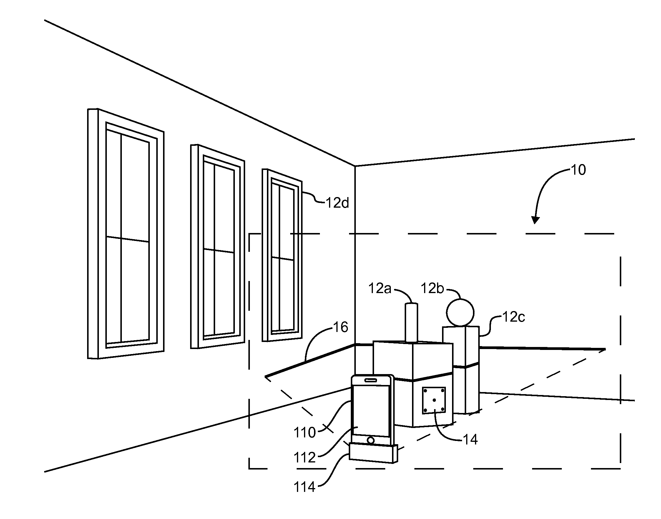
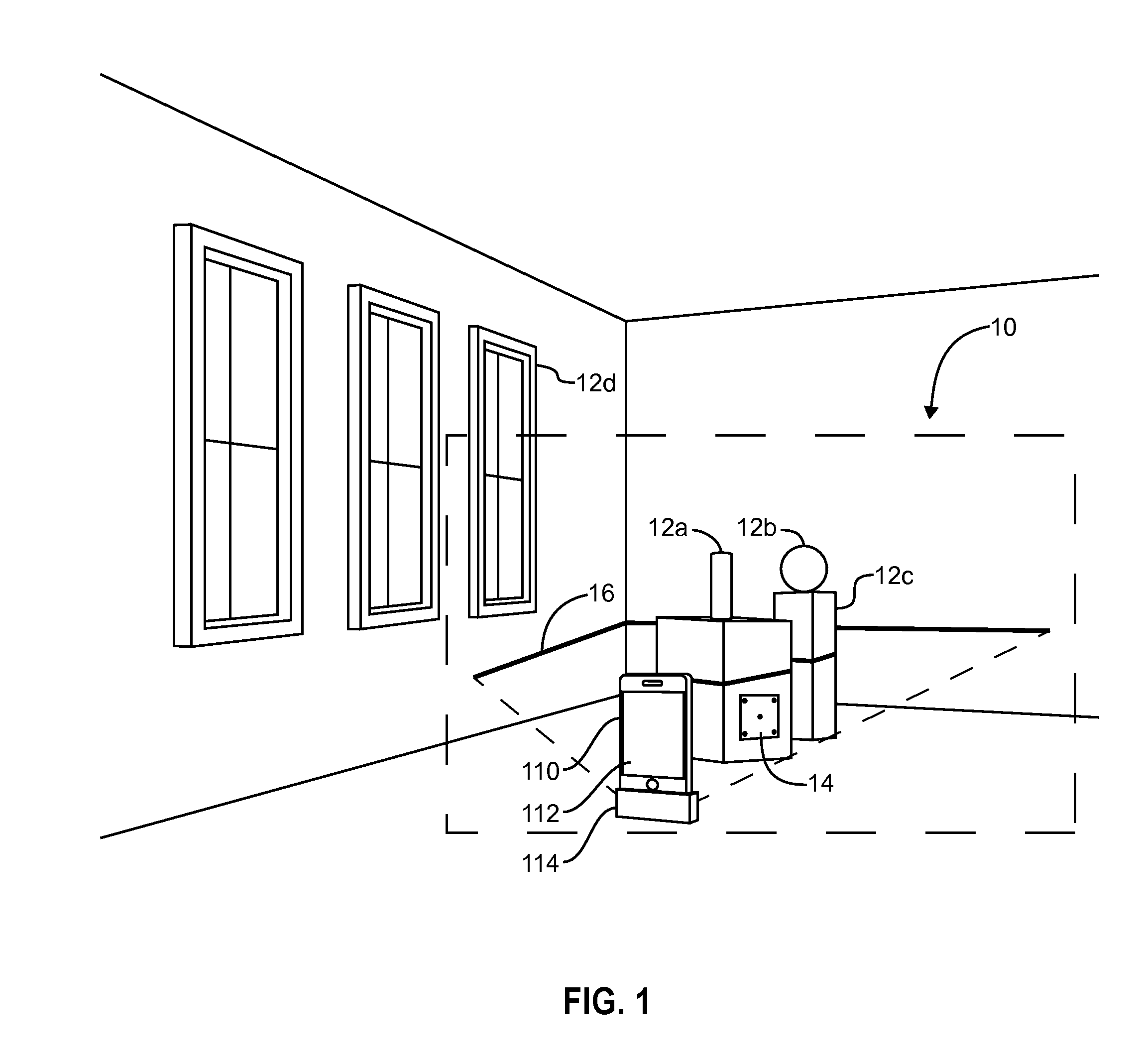
[0081]In the image capture system, the Camera(s) must be mechanically linked to the Active Illumination device(s). In the embodiment 110 illustrated in FIG. 1 the mechanical linkage is based on both the camera 112 and active illumination device 114 being in physically attached to each other. In addition to being mechanically linked, it is preferable though not essential that the Camera and Active Illumination devices are Electrically linked.

[0082]How the Invention Works.

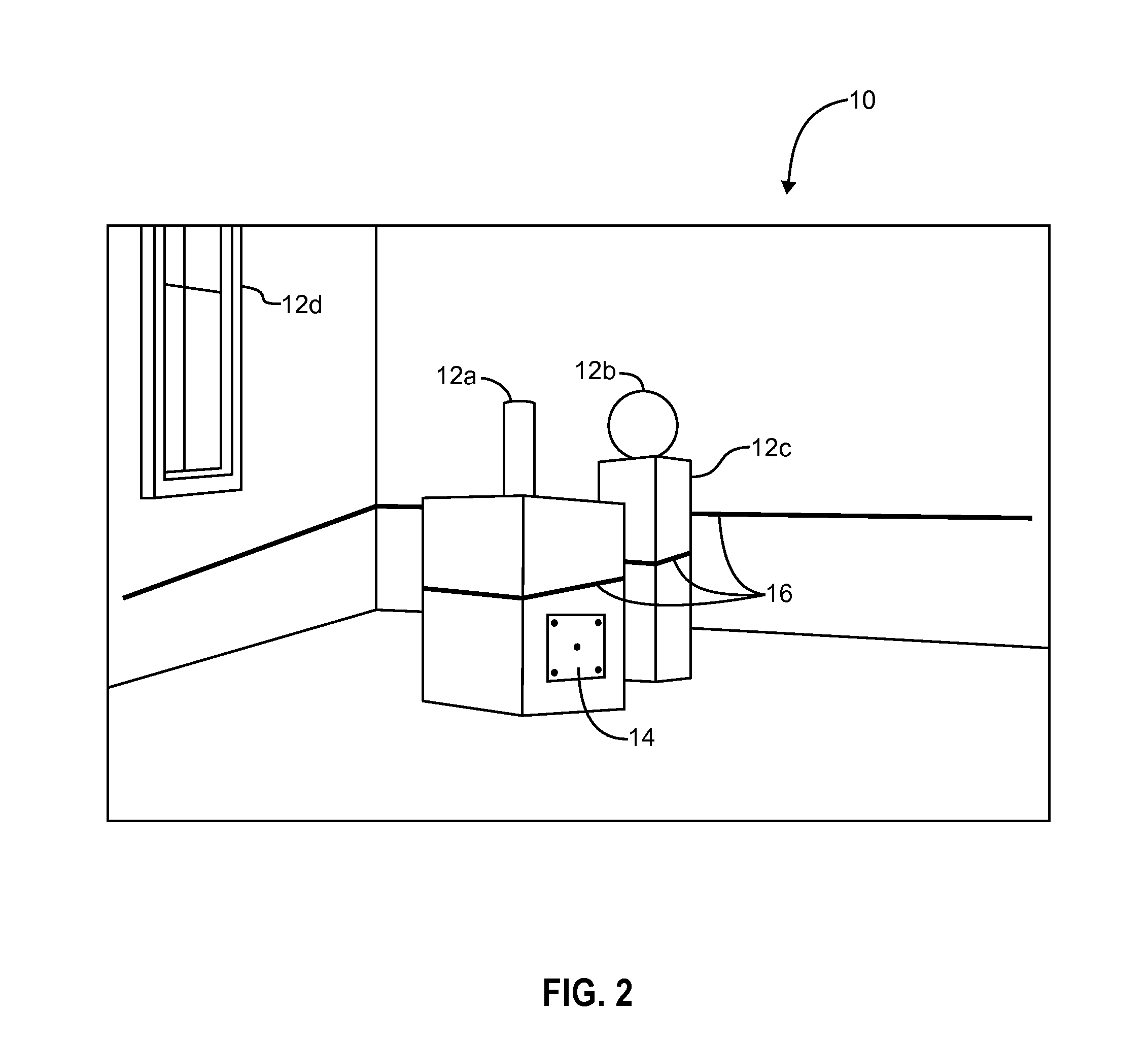
[0083]FIG. 18 provides a review of the forgoing description of the hardware for a discussion of how the hardware is employed to generate a 3D surface model of an object. The drawing is similar to FIG. 1 but shows a different pose and position of the camera (more angled down). The operation of the invention is diagrammed in the flow chart included as FIG. 19 which provides a simplified flow diagram for processing the multiple image frames into a single 3D model.

[0084]At least one reference template is placed in the sc...

second embodiment

[0089]In a second embodiment, the projected light pattern serves as the reference template. The camera and attached light pattern projector moves around the scene capturing a sequence of images containing the projected reference template and the scene of interest. This embodiment uses a scale defining method based on the projected reference template in combination with real time structure from motion (RTSLM) or synchronized localization and mapping (SLAM) or similar 3D structure from motion (SFM) approach to define scale in a dense 3D image. As before, the pose and position of the camera is determined with minimal processing from the view of the reference template in each image frame. This enables the detailed measurement across the entire 3D model as calibrated from the scale defining method.

[0090]In a third embodiment, a physical reference template is placed into the scene as in the first embodiment, and there is no projected light pattern. The camera moves around the scene captur...


PUM


Abstract

3D Modeling System and Apparatus for mobile devices with limited processing capability is disclosed. This invention uses the standard camera and computing resources available on consumer mobile devices such as smart phones. A light projector (e.g. laser line generator) is attached as an accessory to the mobile device or built as a part of the mobile device. Processing requirements are significantly reduced by including known object(s) or reference template(s) in the scene to be captured which are used to determine the pose/position of the camera relative to the object or scene to be modeled in a series of camera pose/position sequences. The position/pose of the camera and projector for each sequence is facilitated by image distortions of known dimensions of reference template or known object in a sequence of captured images.

Description

RELATED APPLICATION[0001]This application is a utility application claiming priority of United States provisional application(s) Ser. No. 61 / 732,636 filed on 3 Dec. 2012; Ser. No. 61 / 862,803 filed 6 Aug. 2013; and Ser. No. 61 / 903,177 filed 12 Nov. 2013 U.S. Utility application Ser. No. 13 / 861,534 filed on 12 Apr. 2013; and Ser. No. 13 / 861,685 filed on 12 Apr. 2013; and Ser. No. 14 / 308,874 filed Jun. 19, 2014; and Ser. No. 14 / 452,937 filed on 6 Aug. 2014.TECHNICAL FIELD OF THE INVENTION[0002]The present invention generally relates to optical systems, more specifically to electro-optical systems that are used to determine the camera position and pose relative to the photographed scene in order to extract correct dimensions of objects from photographic images.BACKGROUND OF THE INVENTION[0003]The present invention relates generally to three-dimensional (“3D”) modeling and more specifically it relates to an image data capture and more particularly, to a combination of processing systems,...

Claims


Application Information

Patent Timeline
IPC IPC(8): H04N13/02H04N13/00
CPCH04N13/0275H04N13/0282H04N13/0296H04N13/0055G01B11/25G01B21/042G06T17/05H04N13/254
Inventor JOVANOVIC, DEJANBEARDMORE, KEITHMYLLYKOSKI, KARIFREEMAN, MARK O.
Owner JOVANOVIC DEJAN
Why Eureka
Try Eureka