
Isothermal-turbo-compressor-expander-condenser-evaporator device

a technology of compressor and compressor, which is applied in the field of air conditioning, heating, heat pump, refrigeration, can solve the problems of increasing component count and cost, reducing efficiency, and requiring more energy for compression and heat expulsion until the completion of compression, so as to achieve the effect of reducing air leakag

Inactive Publication Date: 2016-05-19
APPOLLO WIND TECH
View PDF6 Cites 7 Cited by
  • Summary
  • Abstract
  • Description
  • Claims
  • Application Information

AI Technical Summary

Benefits of technology

The patent describes a device called a "turbo-compressor-condenser-expander-evaporator" (TCCEE) that is used for refrigeration. The device has three main stages: a compressor, a condenser, and an expander. The compressor stages compress the refrigerant using two different methods, and the condenser and expander stages expand and evaporate the refrigerant. These stages are all arranged in a way that allows for efficient heat transfer and air flow. The device is powered by a rotating central axle that drives the air flow through the system. The invention also includes a plenum that collects and directs the air flow, and an insulated barrier disc to minimize air leakage. Overall, the technical effects of the invention are improved refrigeration efficiency and the ability to compress, cool, and evaporate refrigerant in a compact space.

Problems solved by technology

A disadvantage to conventional air-conditioning and heat pump arrangements that employ an evaporative / condensing, phase-changing compound, such as refrigerant arrangement is that they require a compressor to first pressurize the refrigerant so that it becomes a high-pressure, heated gas, a condenser for providing the heat exchange required to cool down the refrigerant before it passes into the coil within the refrigerant compartment, and an expansion valve.
This reduces efficiency and increases component count and cost.
Thus, compression with delay of heat expulsion until completion of the compression requires more energy than compression with anticipated heat expulsion during the compression.
However, these systems typically require an increased component count relative to a conventional arrangement—for example a first-stage compressor, flash chamber, heat exchanger, and second-stage compressor.
These multi-stage systems have typically been limited to large-scale refrigeration systems due to the number of components (and associated higher cost) required for operation.
This cost and complexity renders such systems, undesirable for smaller scale air-conditioning and refrigeration applications, or those deployed in a relatively confined space, such as a window air conditioner, or automotive air conditioning system.
However, these compressors operate with a reciprocating piston that does not allow sufficient physical proximity between the refrigerant under compression (inside the piston chamber) and the fluid (such as atmospheric air) used for the cooling, and only a fraction of the heat can be extracted during the compression.
Thus, these (and other prior art systems) do not allow for a large portion of cooling (and condensation) to desirably occur during the compression cycle to improve efficiency.
In various implementations, rotary fluid unions can incur additional frictional losses and potentially pose a leak point for emissions of environmentally deleterious refrigerants if they are utilized.
Such rotary fluid unions may also limit the maximum operating pressures for refrigerant fluids, and hence can limit potential refrigerant selection to those with greater-than-ambient absolute pressure while operating to prevent leaks inward with resultant refrigerant contamination.
Additionally, the devices described in the '733 patent may be directed more toward a limited number of operating points over a range of refrigeration capacity, making this arrangement less-suited to certain implementations in which a wide operating range is desired (e.g. window air conditioners and automotive units).
The refrigeration process disclosed in the '733 patent is also inherently limited from reaching the maximum efficiency possible, as the pressure range over which the refrigerant is expanded isentropically does not have much work available due to a limited change in volume.

Method used


Image

  • Isothermal-turbo-compressor-expander-condenser-evaporator device
  • Isothermal-turbo-compressor-expander-condenser-evaporator device
  • Isothermal-turbo-compressor-expander-condenser-evaporator device

Examples


Embodiment Construction

I. ITCCEE Structure and Operation

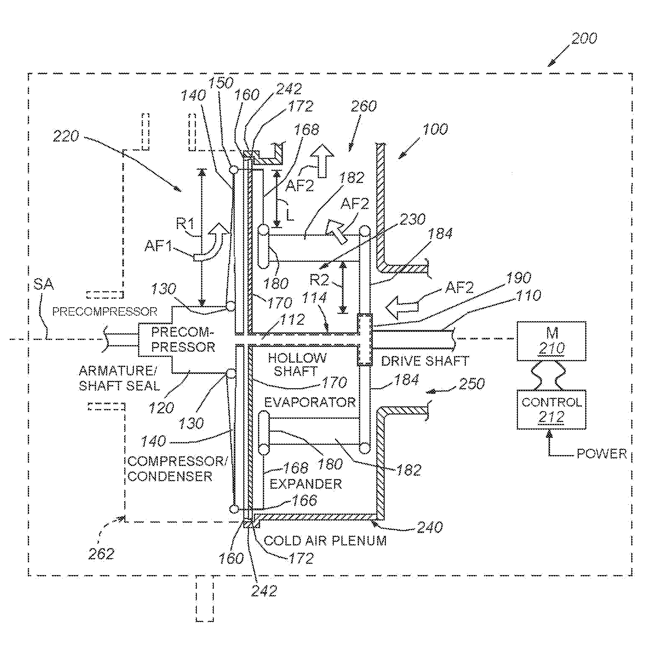
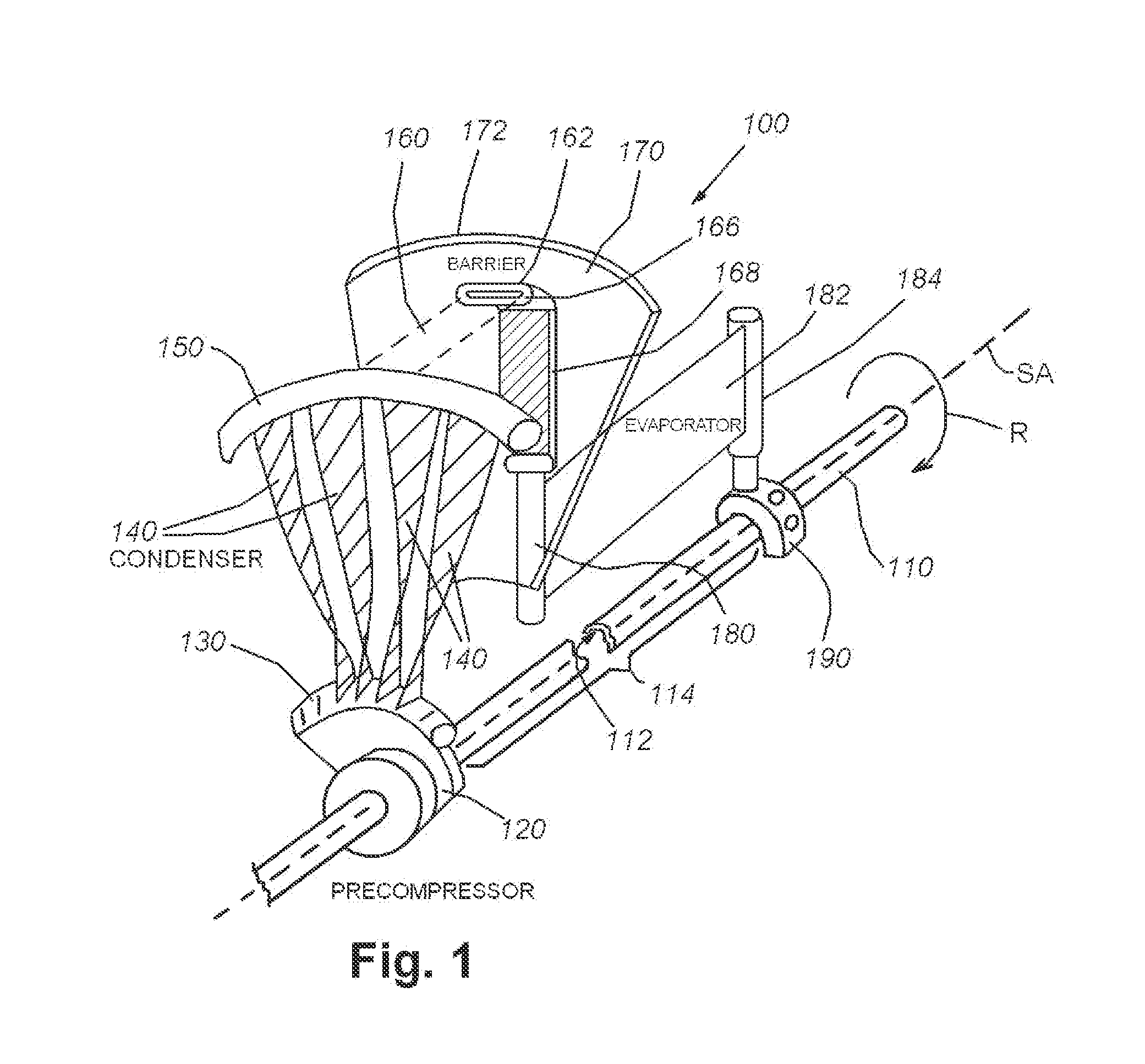
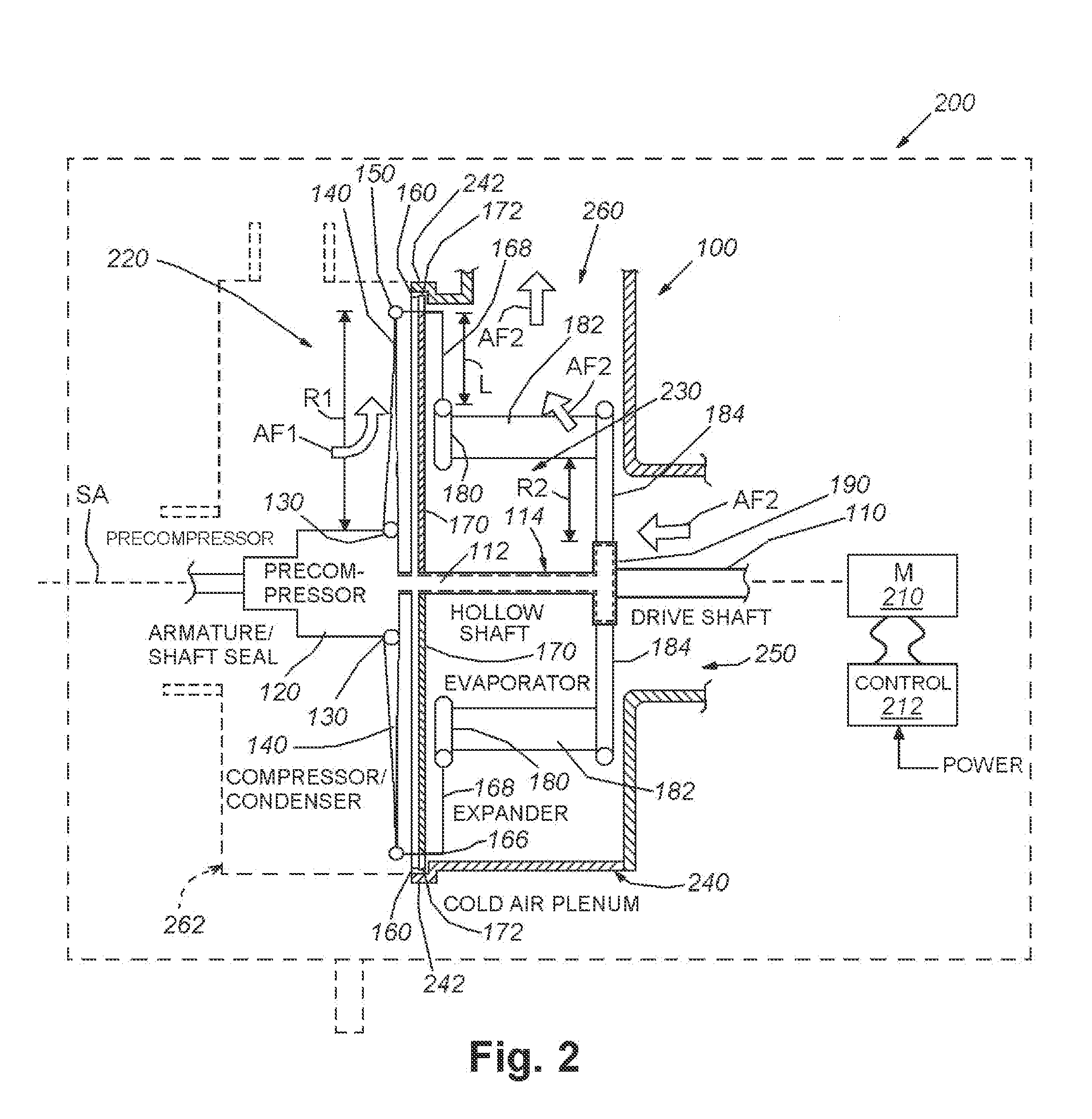
[0022]Reference is made to an isothermal turbo-compressor-condenser-expander-evaporator (ITCCEE) device 100 shown in FIGS. 1 and 2. Similar to the above-incorporated '733 patent, describing an isothermal turbo-compressor-condenser-expander ITCCE, the illustrative ITCCEE is comprised as a rotating air-heat exchange device in which components of the heat-exchange cycle are contained integrally on the same rotating drive shaft. Notably, the illustrative embodiment of the ITCCEE is free of rotary fluid unions for increased reliability, and efficiency. To eliminate the use of rotary fluid unions, the positive displacement precompressor and evaporator are repositioned and integrated with the overall rotating, central axial assembly.

[0023]In this embodiment, the device 100 includes a drive shaft 110 that is operatively connected by any acceptable power transmission assembly to a drive motor 210 that rotates (curved arrow R) the shaft at a fixed, or typicall...


PUM


Abstract

This invention provides an isothermal turbo-compressor-expander-condenser-evaporator in a single integral arrangement that is suitable for a variety of compact arrangements, such as a window air-conditioner and / or automotive-based unit. This arrangement avoids the use of rotary fluid joints and maintains the entire fluid cycle, including compression, condensation, expansion and evaporation within a single rotating shaft-based structure, with the compressor / condenser section and the expansion / evaporator section separated from each other in separate spaces and / or plena by a rotating, insulated barrier disc and associated seal.

Description

RELATED APPLICATION[0001]This application claims the benefit of co-pending U.S. Provisional Application Ser. No. 62 / 080,996, entitled ISOTHERMAL-TURBO-COMPRESSOR-EXPANDER-CONDENSER-EVAPORATOR DEVICE, filed Nov. 17, 2015, the entire teaching of which is expressly incorporated herein by reference.FIELD OF THE INVENTION[0002]This invention relates to air conditioning, heating, heat pumps, refrigeration, and similar heat-exchange devices, and more particularly to devices capable of being contained in a limited spaceBACKGROUND OF THE INVENTION[0003]A disadvantage to conventional air-conditioning and heat pump arrangements that employ an evaporative / condensing, phase-changing compound, such as refrigerant arrangement is that they require a compressor to first pressurize the refrigerant so that it becomes a high-pressure, heated gas, a condenser for providing the heat exchange required to cool down the refrigerant before it passes into the coil within the refrigerant compartment, and an ex...

Claims


Application Information

Patent Timeline
Patent Type & Authority Applications(United States)
IPC IPC(8): F24F1/02
CPCF24F1/025F24F1/027F25B3/00B60H1/3223
Inventor SWETT, PETER A.
Owner APPOLLO WIND TECH
Learn More