
Control valve

Active Publication Date: 2016-05-19
FIMCIM
View PDF8 Cites 7 Cited by
  • Summary
  • Abstract
  • Description
  • Claims
  • Application Information

AI Technical Summary

Benefits of technology

The patent describes a valve that can be used to control the flow of a fluid. The valve has a mechanism called a flow shutter which can be rotated to choose the number of windows and the size of the passage that faces the inlet slot. The flow shutter can also be moved back and forth to adjust the area of the already facing windows. This mechanism ensures that the valve can effectively clean and regulate the flow of the fluid passing through it.

Problems solved by technology

The Applicant has observed that the valves of the prior art equipped with automatic regulation and flow rate control, such as the one described in document EP 2 338 093, are structurally highly complex and for this reason also very expensive and cumbersome, precisely because they comprise various moving parts dedicated to the respective functions.
The Applicant has also observed that said complexity impacts negatively on regularity of the flow which passes through it, since the liquid must necessarily transit in tortuous conduits and / or flow over structural elements, such as springs, with variable geometry or the configuration of which is not constant in all valve operating conditions.

Method used


Image

  • Control valve
  • Control valve
  • Control valve

Examples


Embodiment Construction

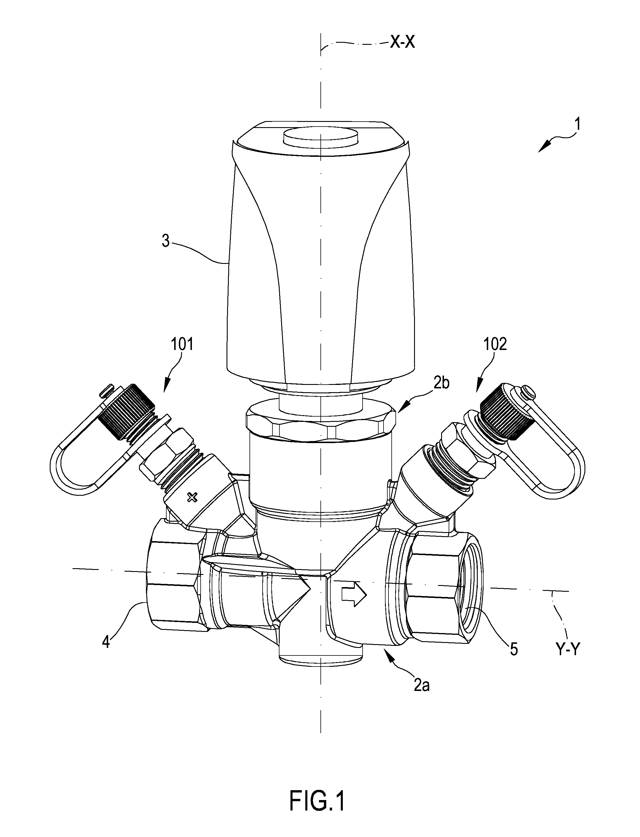
[0067]With reference to FIG. 1, the number 1 denotes in its entirety a control valve comprising a valve body 2 and an actuator 3 mounted on the valve body 2. The valve body 2 has an inlet 4 and an outlet 5 for flow of a liquid. Said inlet 4 and outlet 5 are threaded internally for connection to respective pipe ends.

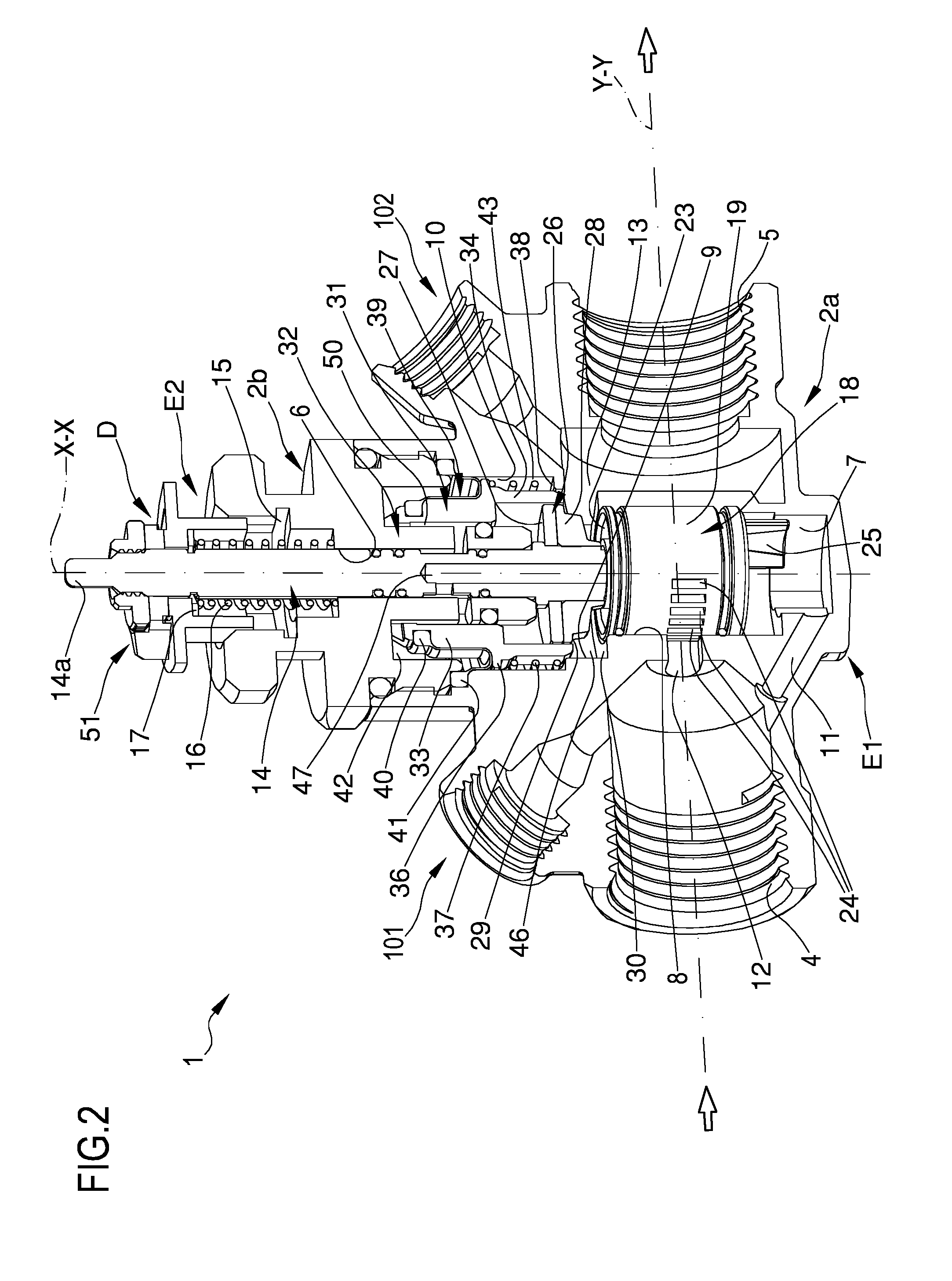
[0068]As visible in FIGS. 2, 4 and 5, the valve body 2 has a principal body 2a afforded in a single piece and having said inlet 4 and said outlet 5 aligned along a flow direction “Y-Y”. The valve body 2 comprises an auxiliary body 2b screwed onto the principal body 2a and having an axial passage 6 which develops along a principal axis “X-X”. The principal body 2a of the valve body 2 delimits internally, in addition to the inlet 4 and to the outlet 5, a substantially cylindrical cavity which develops along said principal axis “X-X” and is formed by several axial cross-sections, as detailed here below. In the embodiment shown, the principal axis “X-X” is perpendicular to th...


PUM


Abstract

A control valve including: a valve body, a flow shutter operatively interposed between an inlet and an outlet, a driving spindle having at least a first actuating end and a second end connected to the flow shutter. The valve also includes a differential pressure automatic regulation device, comprising: a cup-shaped body arranged around the driving spindle and axially mobile with respect to said driving spindle; a spring operatively interposed between the valve body and the cup-shaped body to push the latter away from the flow shutter; a rolling membrane having a radially inner edge fixed to the cup-shaped body and a radially outer edge fixed to the valve body to delimit a first chamber in fluid communication with the inlet and a second chamber in fluid communication with the outlet.

Description

1. TECHNICAL FIELD[0001]The present invention relates to a control valve. In particular, the present invention relates to a valve capable of guaranteeing a constant flow automatically, independently of any fluctuations in pressure upstream or downstream of the valve itself. Said valves are preferably used in heating systems also of highly different dimensions, such as central heating systems in residential units or district heating systems capable of supplying heat to entire districts and / or small towns, and / or cooling systems.2. STATE OF THE ART[0002]Control valves provided with membrane sensitive elements are known which, on the basis of a differential pressure signal, regulate a passing port so as to maintain the differential pressure and the flow rate substantially constant as the incoming or outgoing pressure varies.[0003]Said valve type is described, for example, in document EP 2 338 093 (WO 2009 / 135490) and comprises a device adapted to maintain a constant differential pressu...

Claims


Application Information

Patent Timeline
IPC IPC(8): G05D7/00F16K5/04
CPCF16K5/04G05D7/00F16K3/262G05D7/0106F24D19/1015F24D2220/0271F16K3/26F24D19/10G05D7/06
Inventor GUIDETTI, TIZIANOCERUTTI, ALFREDOCRIVELLI, STEFANO
Owner FIMCIM
Features
  • Generate Ideas
  • Intellectual Property
  • Life Sciences
  • Materials
  • Tech Scout
  • Unparalleled Data Quality
  • Higher Quality Content
  • 60% Fewer Hallucinations
Learn More