System and method for imaging device modelling and calibration

Active Publication Date: 2016-05-19
MARTIN GUY
View PDF6 Cites 36 Cited by
  • Summary
  • Abstract
  • Description
  • Claims
  • Application Information

AI Technical Summary

Benefits of technology

[0006]The proposed calibration and modeling technique introduces an accurate perspective correction to account for assembl

Problems solved by technology

However, this assumption has proven to bias every camera pa

Method used


Image

  • System and method for imaging device modelling and calibration
  • System and method for imaging device modelling and calibration
  • System and method for imaging device modelling and calibration

Examples


Embodiment Construction

1.1 Lens Distortion

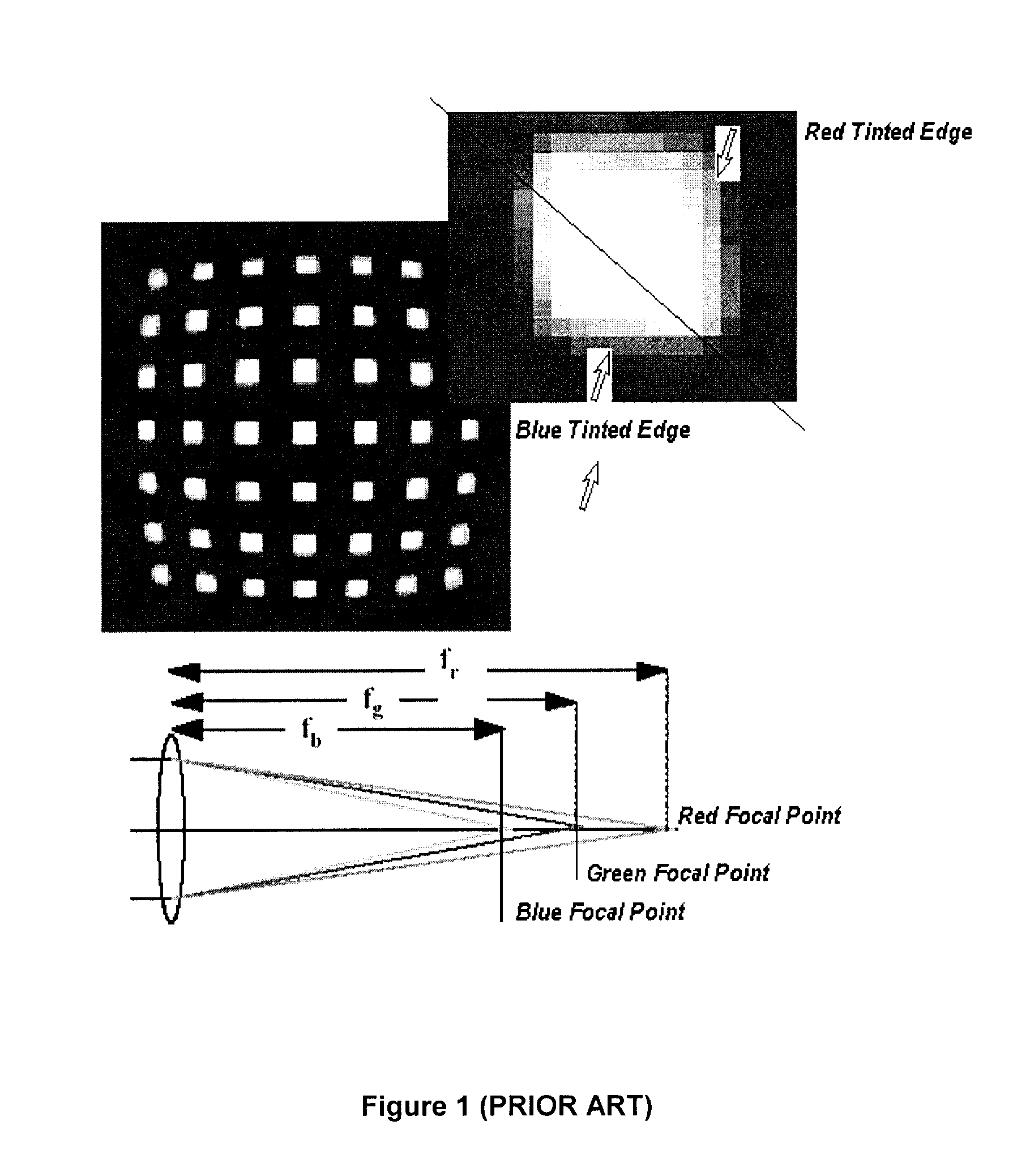
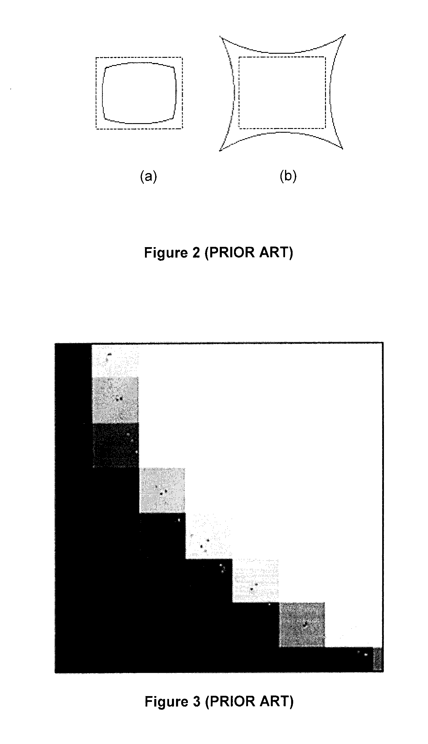
[0050]Lens distortion introduces the biggest error found in digital imaging. This is illustrated in FIGS. 1 and 2. As can be seen in FIG. 1, the fish eye effect is referred to as geometric distortion and curves straight lines. Coloured shading at the edges of the image (referred to as > and > in FIG. 1) is referred to as chromatic distortion and is caused by the splitting of light in the lens of the imaging device (not shown). These deviations from pinhole behaviour increase with the lens angle of view. Both distortions have to be modeled and compensated for to achieve sub-pixel accuracy, compensation possible only through software to go beyond hardware capabilities. As can be seen in FIG. 2, when geometric distortion compresses the image on itself, it is referred to as barrel distortion (see FIG. 2 (a)); when the image expands, it is referred to as pincushion distortion (see FIG. 2 (b)).

1.2 Dithering

[0051]With reference to FIG. 3, dithering is the intermediate pi...


PUM


Abstract

The invention relates to a camera modeling and calibration system and method using a new set of variables to compensate for imperfections in line of sight axis squareness with camera plane and which increases accuracy in measuring distortion introduced by image curvature caused by geometric and chromatic lens distortion and wherein the camera image plane is represented from a full 3D perspective projection.

Description

CROSS-REFERENCE TO RELATED APPLICATIONS[0001]This patent application claims priority of Canadian Application Serial No. 2,819,956, filed on Jul. 2, 2013.TECHNICAL FIELD[0002]The present invention relates to a system and method for imaging device modeling and calibration that compensates for imperfections in line of sight axis squareness with the image plane of the imaging device.BACKGROUND[0003]Calibration of digital cameras and other imaging devices seeks to create a mathematical model of how the image ‘prints’ through the lens on the imaging device's surface. The procedure first uses a picture from a calibration target with accurately known tolerance, and extracts target elements from the image. Finally, a mathematical model relates the image information with the real three-dimensional (3D) target information. Once calibrated, the imaging device can then be used to map real world objects using a scale factor, the focal distance f. When working from off-the-shelf cameras and lenses...

Claims


Application Information

Patent Timeline
IPC IPC(8): G06T7/00G06T5/00H04N17/00
CPCG06T7/0018G06T5/006H04N17/002G06T3/0006G06T2207/10024G06T2207/10004G06T7/80H04N25/61H04N25/611H04N23/843H04N25/60
Inventor MARTIN, GUY
Owner MARTIN GUY
Why Eureka
Try Eureka