
Equipment platform system and wafer transfer method thereof

a technology of equipment platform and wafer, which is applied in the direction of program-controlled manipulators, thin material processing, article separation, etc., can solve the problems of increasing the cost of fab fabrication, and achieve the effect of increasing the wafer transfer efficiency

Active Publication Date: 2016-05-19
SHANGHAI INTEGRATED CIRCUIT RES & DEV CENT
View PDF0 Cites 0 Cited by
  • Summary
  • Abstract
  • Description
  • Claims
  • Application Information

AI Technical Summary

Benefits of technology

The present invention provides an equipment platform system for wafer processes that allows for more process chambers to be mounted on, leading to increased wafer transfer efficiency. The system utilizes a top-loading wafer device that allows for the direct transfer of wafers between the loading unit and the working platform, ensuring a stable vacuum state during processing. The system also includes a shut off gate and a loading gate that work together to ensure the vacuum state of the working platform is maintained. The use of this top-loading wafer device decreases floor space, increases space availability, and increases the number of process chambers mounted on the working platform, leading to uninterrupted multi-step processing and increased transfer efficiency.

Problems solved by technology

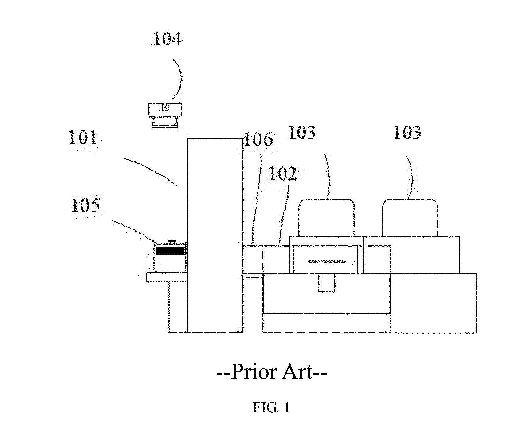
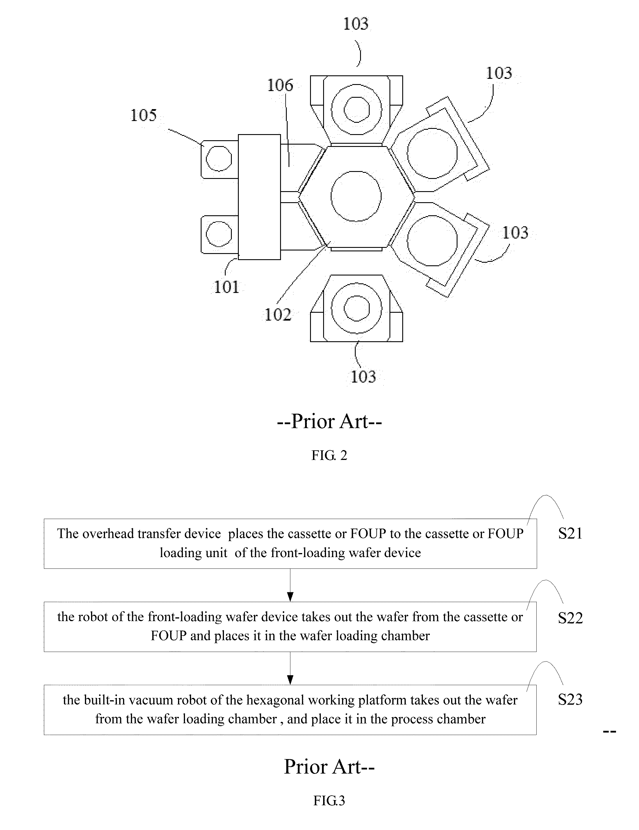
With the development of semiconductor IC manufacturing technology, the wafer size increases from 150 mm, 200 mm to 300 mm or even bigger, the manufacturing cost of FAB is becoming more and more expensive.

Method used


Image

  • Equipment platform system and wafer transfer method thereof
  • Equipment platform system and wafer transfer method thereof
  • Equipment platform system and wafer transfer method thereof

Examples


embodiment one

[0079]Hereinafter with reference to FIG. 4 to FIG. 7, the equipment platform system used for processing the wafers is explained in further detail by a first embodiment of the invention. It should be pointed out that all appended drawings adopt a very simplified form and imprecise scaling is merely used to assistant explain the embodiment of the invention conveniently and clearly.

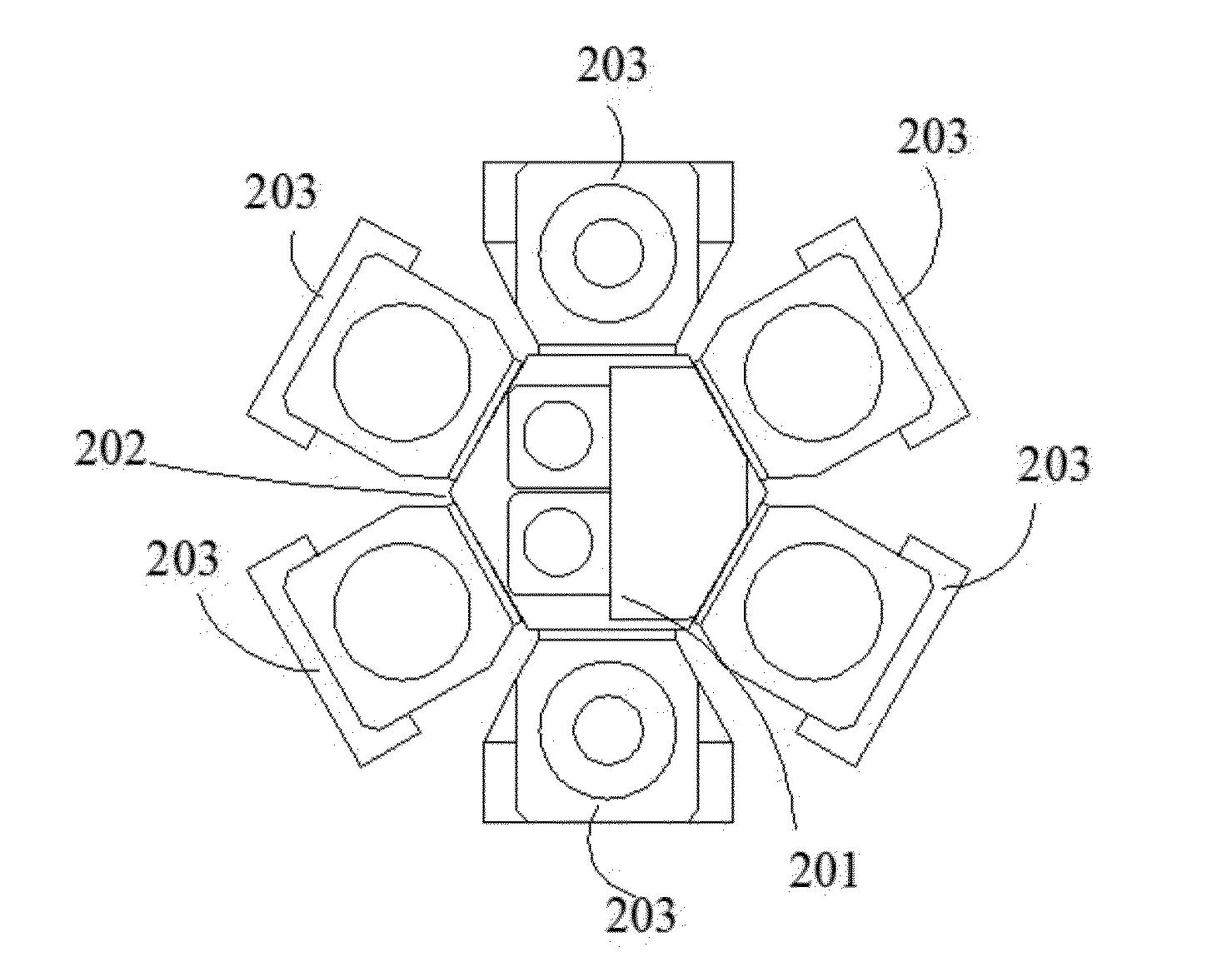
[0080]Please referring to FIG. 4 and FIG. 5, FIG. 4 is a front view illustrating an equipment platform system according to the first embodiment of the present invention, FIG. 5 is a top view of the equipment platform system according to the first embodiment of the present invention. The working platform of the invention can, but not limited to, be a polygon working platform, such as a quadrilateral working platform, a pentagon working platform, a hexagon working platform, an octagon working platform, etc., an equipment platform system of one embodiment of the invention includes a hexagonal working platform a...

embodiment two

[0104]The above is the explanation of the structure of the equipment platform system according to the first embodiment of the present invention, the following is a further explanation of the wafer transfer method according to a second embodiment of the present invention with reference to FIG. 9 and FIG. 10. It should be pointed out that all appended drawings adopt a very simplified form and imprecise scaling is merely used to assistant explain the embodiment of the invention conveniently and clearly.

[0105]Please referring to FIG. 9, FIG. 9 is a flow diagram illustrating a wafer transfer method according to an embodiment of the present invention. The wafer transfer method according to the embodiment of the present invention adopts the above-mentioned the equipment platform system as an example, the wafer transfer method includes a multi-wafer input procedure, and the multi-wafer input procedure includes:

[0106]Step 01: the rotatable arm of the central robot takes out the wafer from th...

embodiment three

[0138]With reference to FIG. 11 and FIG. 12, the wafer transfer method according to the present invention will be further explained. It should be pointed out that all appended drawings adopt a very simplified form and imprecise scaling is merely used to assistant explain the embodiment of the invention conveniently and clearly.

[0139]Please referring to FIG. 11, FIG. 11 a flow diagram illustrating a wafer transfer method according to a third embodiment of the present invention. The wafer transfer method according to the preferred embodiment of the invention adopts the above-mentioned equipment platform system, the wafer transfer method includes a multi-wafer input procedure, and the multi-wafer input procedure includes:

[0140]Step 31: the arm of the central robot takes out the wafer from the cassette or FOUP of the cassette or FOUP loading unit.

[0141]In the embodiment of the invention, at first, the overhead transfer device carries the wafer box to the cassette or FOUP loading unit of...


PUM


Abstract

An equipment platform system and a wafer transfer method used to a wafer processing is provided. The equipment platform system comprises: a working platform, each side of the working platform is used to mount process chamber; a top-loading wafer device fixed on the top surface of working platform, the top-loading wafer device includes: a cassette or FOUP loading unit, a wafer loading unit installed disposed opposite the cassette or FOUP loading unit, the wafer loading unit has an inside cavity; a central robot, located between the cassette or FOUP loading unit and the wafer loading unit; a loading gate used to open or close the inside cavity; a wafer tray, which is in the inside cavity; a shutoff gate, which is at the bottom of the inside cavity, used to open or close the internal of the working platform; there is an opening at the top of the working platform, the opening is located at the lower part of the inside cavity, and disposed opposite the shutoff gate, the shutoff gate can seal the opening. The equipment platform system of the invention can decrease the floor space, increase the space efficiency, and the wafer transfer efficiency.

Description

CROSS-REFERENCE TO RELATED APPLICATION[0001]The application claims the priority benefit of International Patent Application Ser. No. PCT / CN2013 / 084249, filed Sep. 26, 2013, which is related to and claims the priority benefit of China patent application Ser. No. 201310332646.5 filed Aug. 1, 2013. The entirety of each of the above-mentioned patent applications is hereby incorporated by reference herein and made a part of the specification.FIELD OF THE INVENTION[0002]The present invention generally relates to the automatic transport field, more particularly, to an equipment platform system and a wafer transfer method thereof.BACKGROUND OF THE INVENTION[0003]With the development of semiconductor IC manufacturing technology, the wafer size increases from 150 mm, 200 mm to 300 mm or even bigger, the manufacturing cost of FAB is becoming more and more expensive. How to effectively exploit the limited production space of the FAB, improve the productivity of production equipment, shorten pro...

Claims


Application Information

Patent Timeline
Patent Type & Authority Applications(United States)
IPC IPC(8): H01L21/67B25J11/00B25J9/04H01L21/677
CPCH01L21/67201H01L21/67781B25J9/042H01L21/67766B25J11/0095H01L21/6719H01L21/67757H01L21/67772H01L21/67775H01L21/67778H01L21/67196
Inventor REN, DAQING
Owner SHANGHAI INTEGRATED CIRCUIT RES & DEV CENT
Learn More