Flyback power converter, secondary side control circuit, and control method thereof

a control circuit and power converter technology, applied in the direction of electric variable regulation, process and machine control, instruments, etc., can solve the problem of undesirable flicker of leds

Active Publication Date: 2016-05-19
RICHTEK TECH
View PDF1 Cites 14 Cited by
  • Summary
  • Abstract
  • Description
  • Claims
  • Application Information

AI Technical Summary

Benefits of technology

[0009]From one perspective, the present invention provides a flyback power converter, for converting an input voltage to an output voltage, and providing a load current to a load circuit, the flyback power converter comprising: a transformer circuit, which includes: a primary winding, for receiving the input voltage; a secondary winding, for generating the output voltage at an output node; and a tertiary winding, for generating a voltage sense signal according to the output voltage; a power switch circuit, which is coupled to the primary winding, for operating a power switch therein according to an operation signal, so as to convert the input voltage to the output voltage; a switch current sense circuit, which is coupled to the power switch circuit, for generating a switch current sense signal according to a switch current flowing through the power switch; a primary side control circuit, which is coupled to the tertiary winding, the switch current sense circuit, and the power switch circuit, for generating the operation signal according to the voltage sense signal, the switch current sense signal, and a feedback signal; and a secondary side control circuit, which is coupled to the output node and the primary side circuit, for generating the feedback signal according to the load current, and adaptively adjusting a frequency of a zero of a compensator gain function and / or a mid-frequency gain of the compensator gain function according to a condition of the load current, such that a number of poles of a system open loop gain function of the flyback power converter is at most more than a number of zeroes of the system open loop gain function by one under a crossover frequency.

Problems solved by technology

As shown in FIG. 1B, when the load circuit 40 is in light load condition, the output voltage Vout and the load current Iload will be conductive intermittently, which will cause flickers of the LEDs that is undesirable.

Method used


Image

  • Flyback power converter, secondary side control circuit, and control method thereof
  • Flyback power converter, secondary side control circuit, and control method thereof
  • Flyback power converter, secondary side control circuit, and control method thereof

Examples


first embodiment

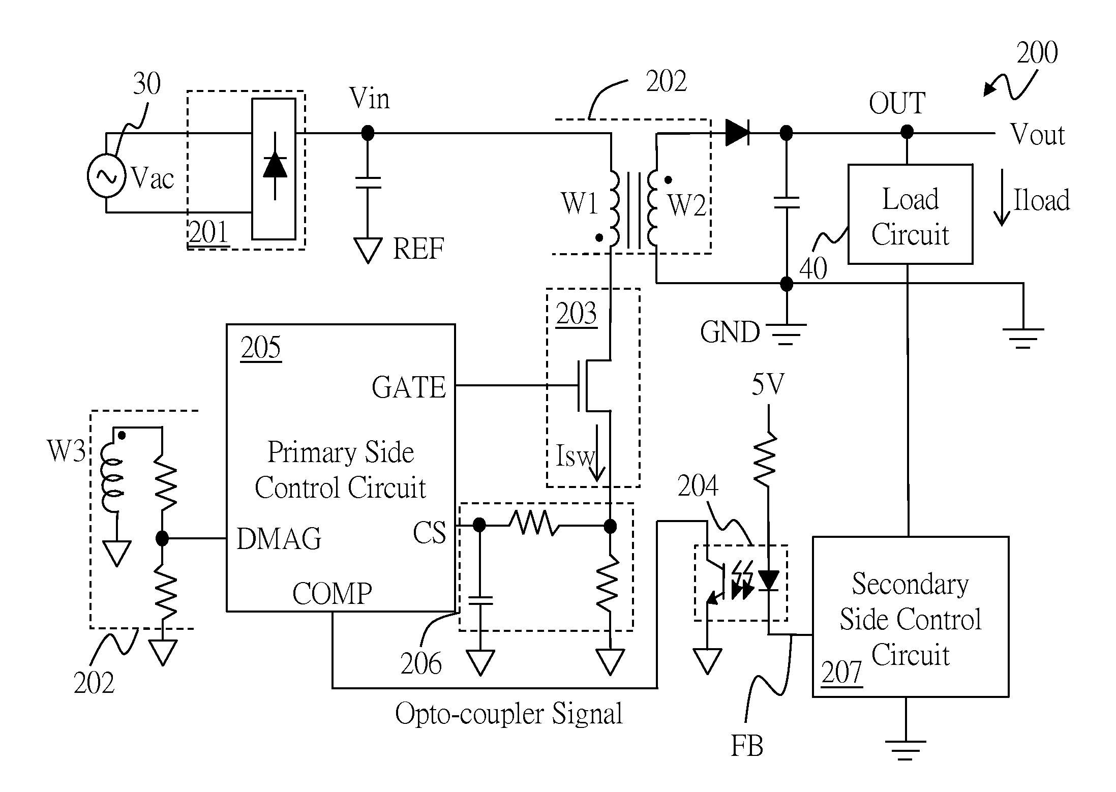
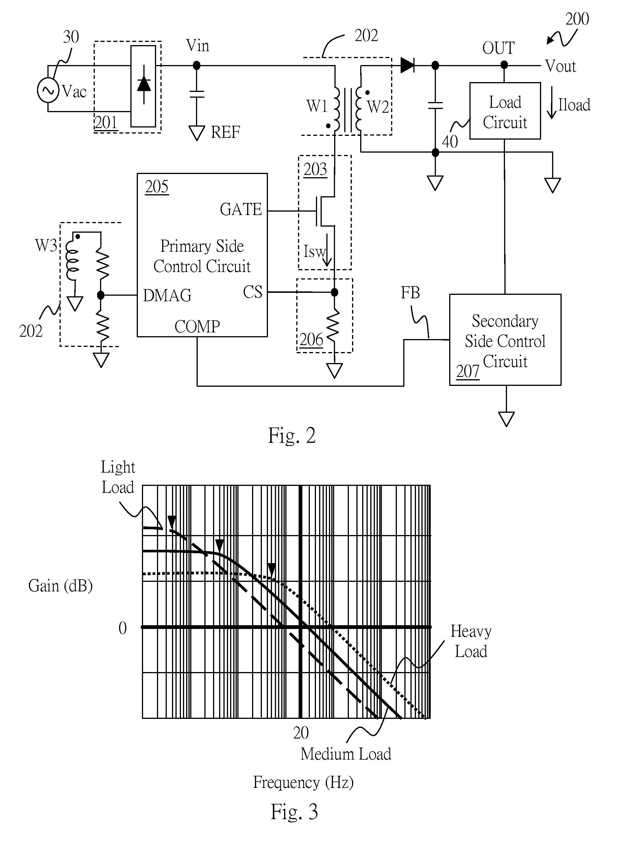
[0041]FIG. 2 shows a first embodiment according to the present invention. As shown in FIG. 2, an AC power source 30 generates an AC voltage Vac. A rectifier circuit 201 rectifies the AC voltage Vac to generate an input voltage Vin. The rectifier circuit is for example but not limited to a bridge rectifier circuit. The flyback power converter 200 converts the input voltage Vin to an output voltage Vout, and provides a load current Iload to a load circuit 40. The flyback power converter 200 includes: a transformer circuit 202, a power switch circuit 203, a primary side control circuit 205, a switch current sense circuit 206, and a secondary side control circuit 207.

[0042]The transformer circuit 202 includes a primary winding W1, a secondary winding W2, and a tertiary winding W3. The secondary winding W2, the secondary side control circuit 207, the tertiary winding W3, and the switch current sense circuit 206 are coupled to a reference level REF. The primary winding W1 is for receiving...

third embodiment

[0055]FIG. 9 shows the present invention, which is an embodiment of the secondary side control circuit 207. As shown in the figure, the secondary side control circuit 207 includes: a current regulator 2071, a load current sense circuit 2072, a transconductance amplifier 2073, and a compensator 2074. The current regulator 2071 is coupled to the load circuit 40, for regulating the load current Iload. The load current sense circuit 2072 is coupled to the current regulator 2071, for sensing the load current Iload and generating a load current sense signal according to the load current Iload. The transconductance amplifier 2073 is coupled to the load current sense circuit 2072, for generating the feedback signal FB according to the load current sense signal, a current adjustment reference signal, and a compensation signal. The compensator 2074 is coupled to the transconductance amplifier 2073, for generating the compensation signal according to the load current Iload. The compensator 207...

fourth embodiment

[0056]FIG. 10 shows the present invention, which is a more specific embodiment of the secondary side control circuit 207. As shown in the figure, in this embodiment, the current regulator 2071 regulates the load current at a current which is equal to Vg / Rcc. The load current sense circuit 2072 for example includes an amplifier A1, which generates the load current sense signal by amplifying a voltage difference between a source and a drain of a switch Q1, which is related to the load current Iload. The load current sense signal is inputted to the transconductance amplifier 2073. The transconductance amplifier 2073 generates the feedback signal FB according to the load current sense signal, a current adjustment reference signal Vdsref, and a compensation signal Vcs. The transconductance amplifier 2073 can optionally further includes a unit gain circuit 2075 as shown in the figure. The compensator 2074 generates the compensation signal Vcs according to the load current Iload (to be exp...


PUM


Abstract

The present invention provides a flyback power converter, a secondary side control circuit, and a control method thereof. The flyback power converter converts an input voltage to an output voltage, and provides a load current to a load circuit. The flyback power converter includes: a transformer circuit, a power switch circuit, a switch current sense circuit, a primary side control circuit, and a secondary side control circuit. The secondary side control circuit adaptively adjusts a frequency of a zero of a compensator gain function and/or a mid-frequency gain of the compensator gain function according to the load current, such that a number of poles of a system open loop gain function of the flyback power converter is at most more than a number of zeroes of the system open loop gain function by one under a crossover frequency.

Description

CROSS REFERENCE[0001]The present invention claims priority to U.S. 62 / 081,194, filed on Nov. 18, 2014.BACKGROUND OF THE INVENTION[0002]1. Field of Invention[0003]The present invention relates to a flyback power converter, a secondary side control circuit, and a control method thereof; particularly, it relates to such flyback power converter which adaptively adjusts a frequency of a zero of a compensator gain function and / or a mid-frequency gain of the compensator gain function according to a load current, and a secondary side control circuit and a control method thereof.[0004]2. Description of Related Art[0005]In applications of a power converter for providing power to a motor or a light emitting device (LED) circuit, a two-stage power converter is often required in order to achieve power factor correction (PFC) and to provide an adjustable output voltage (e.g., switchable between different levels such as 5V, 12V, and 24V etc.). For example, as shown in FIG. 1A, an AC power supply 3...

Claims


Application Information

Patent Timeline
Patent Type & Authority Applications(United States)
IPC IPC(8): H02M3/335
CPCH02M2001/0009H02M3/33523H02M1/4258H02M1/0009H02M1/0025H02M1/0032Y02B70/10
Inventor HUANG, CHUN-SHIHWU, CHANG-YUCHEN, PEI-YUAN
Owner RICHTEK TECH
Why Eureka
Try Eureka