Supercharge Your Innovation With Domain-Expert AI Agents!

Method and apparatus for automated connection of a fluid conduit

a technology of fluid conduits and automatic connection, which is applied in the direction of drilling pipes, drilling casings, borehole/well accessories, etc., can solve the problems of difficult access for personnel to easily access cement heads, top drive hoses and/or ancillary equipment, and cement slurry hardening within the top drive unit, etc., to facilitate the flow of pressurized fluids.

Active Publication Date: 2016-05-26
FRANKS INT
View PDF9 Cites 2 Cited by
  • Summary
  • Abstract
  • Description
  • Claims
  • Application Information

AI Technical Summary

Benefits of technology

The automated system enhances safety by reducing manual handling risks, ensures reliable and efficient connection of fluid conduits to elevated cement heads, and maintains a secure fluid pressure seal during operations, thereby improving operational efficiency and safety.

Problems solved by technology

However, when drilling from a floating drilling vessel, blowout preventer and wellhead assemblies are not located on the drilling rig, platform or other structure; rather, such assemblies are located at or near the sea floor.
However, such a configuration is not preferred for cementing operations, because an unexpected loss of power or pumping shut down could result in cement slurry hardening within the top drive unit, top drive hoses and / or ancillary equipment.
In many instances, a cement head will typically be positioned at an elevated position out of reach of personnel working on a rig floor, thereby making it difficult for such personnel to easily access the cement head in order to connect chiksans, flow lines and / or other fluid conduits to said cement head.
When this occurs, such personnel are at risk of falling and suffering serious injury or death.
Moreover, such personnel are frequently required to carry heavy hammers, wrenches and / or other tools used to facilitate connection of the flow conduit to the cement head inlet, thereby increasing the risk of such items being accidentally dropped on personnel and / or equipment positioned on the rig floor below.

Method used


Image

  • Method and apparatus for automated connection of a fluid conduit
  • Method and apparatus for automated connection of a fluid conduit
  • Method and apparatus for automated connection of a fluid conduit

Examples


Embodiment Construction

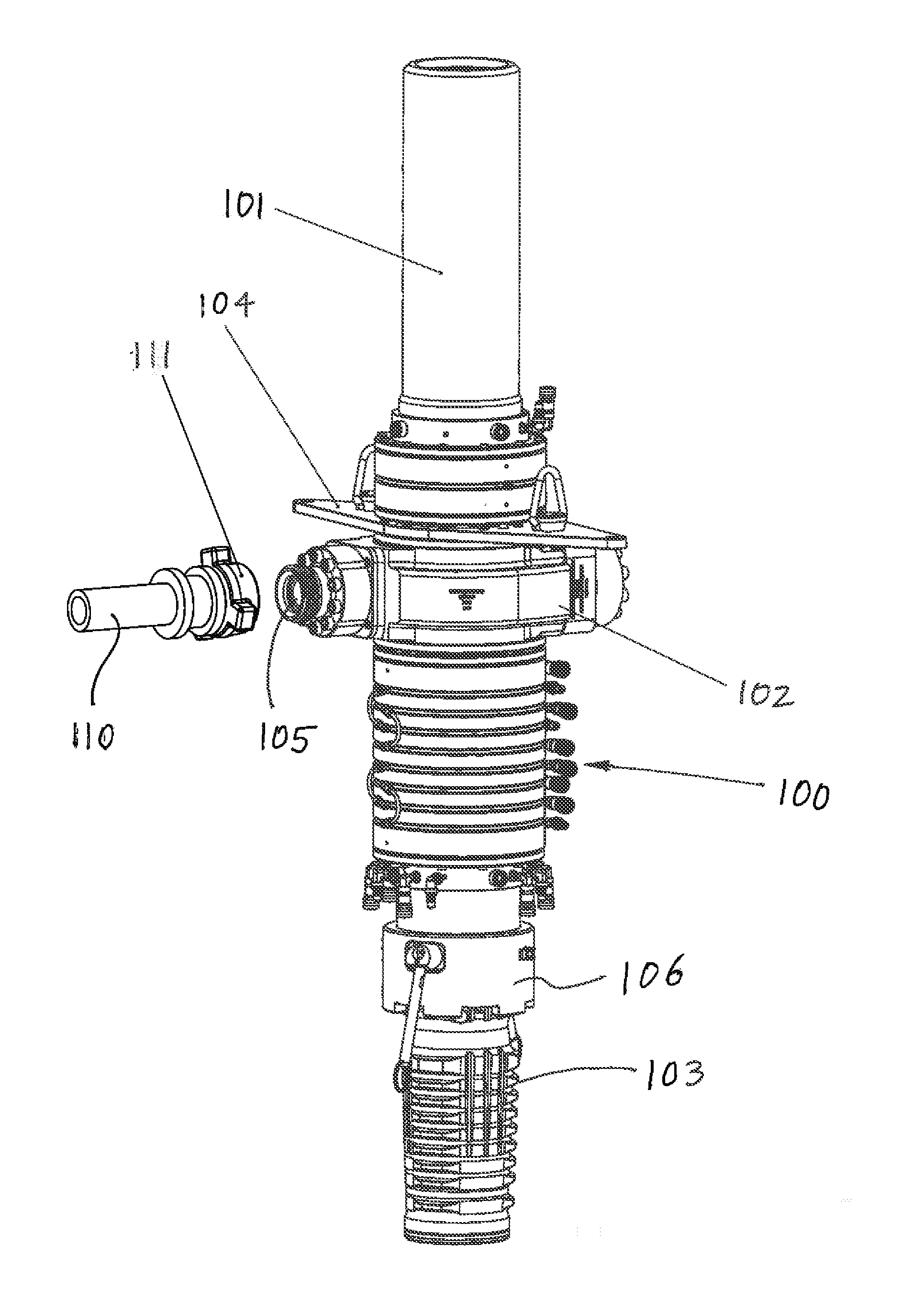
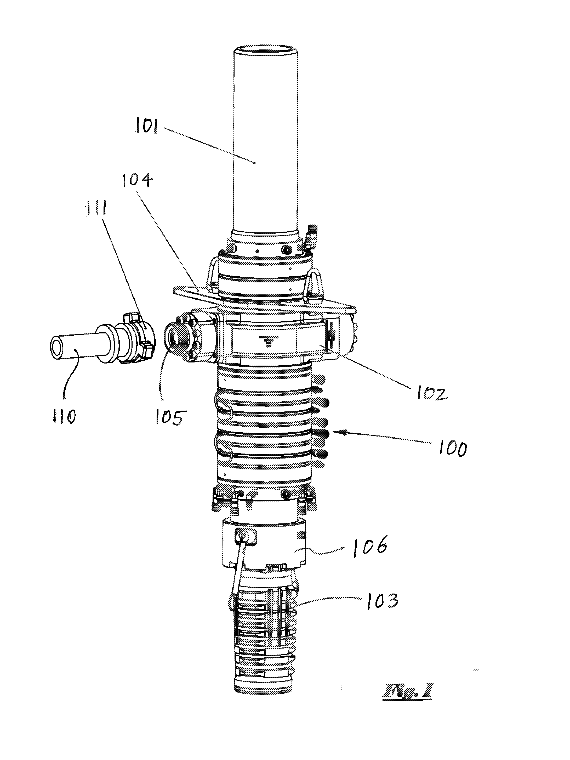
[0042]Referring to the drawings, FIG. 1 depicts a side perspective view of an upper portion of a conventional top-drive cement head assembly 100. Said cement head assembly 100 generally comprises upper body member 101 which can be attached to a lower connection of a rig's top drive unit or other equipment (not pictured), as well as lower connection member 103 having lower connection hub 106 which can be attached to other cementing components or equipment, such as other cement head assembly components well known to those having skill in the art.

[0043]Cement head assembly 100 further comprises swivel assembly 102 having a fluid inlet 105 well known to those having skill in the art, as well as torque plate 104. Said torque plate 104 can be chained or otherwise secured to a rig component or other stationary object to permit rotation of cement head assembly 100, while securing non-rotating components of said cement head assembly 100. It is to be observed that cement head assembly 100 as ...


PUM


Abstract

A connection assembly for automated lifting and positioning of a chiksan or other fluid conduit in proximity to a fluid inlet of a device such as, for example, a cement head. Once a chiksan or other flow line is positioned in a desired location, a secure connection is made between the outlet of the chiksan or other fluid conduit and the fluid inlet of a cement head including, without limitation, when the cement head is positioned at an elevated location above a rig floor.

Description

BACKGROUND OF THE INVENTION[0001]1. Field of the Invention[0002]The present invention pertains to an automated assembly for connecting a fluid flow line to an inlet port. More particularly, the present invention pertains to an automated assembly for connecting a fluid flow line (such as a chiksan, hose or other conduit) to an inlet port of a cement head assembly.[0003]2. Brief Description of the Related Art[0004]Many offshore oil and / or gas wells are drilled in marine environments using floating vessels (such as, for example, drill ships and semi-submersible drilling rigs), particularly prior to installation of a permanent platform or other similar structure. Drilling operations conducted from such floating vessels differ from those conducted from permanent structures in many respects.[0005]One important difference associated with drilling from a floating vessel is the location of blowout preventer and wellhead assemblies. When drilling from a fixed platform or other similar structu...

Claims


Application Information

Patent Timeline
Patent Type & Authority Applications(United States)
IPC IPC(8): E21B19/00E21B19/22
CPCE21B19/22E21B19/008E21B33/05E21B21/02E21B19/16
Inventor MARTENS, JAMES G.HEBERT, JOHN E.ROBICHAUX, RON D.MONDELLI, JUAN CARLOS E.CHAMPAGNE, JAMESBOUDREAUX, JOSEPHSCOTT, SCOTTIE J.LECOMPTE, JEREMY
Owner FRANKS INT
Features
  • R&D
  • Intellectual Property
  • Life Sciences
  • Materials
  • Tech Scout
  • Unparalleled Data Quality
  • Higher Quality Content
  • 60% Fewer Hallucinations
Learn More