Cooling channel for airfoil with tapered pocket

a cooling channel and airfoil technology, applied in waterborne vessels, climate sustainability, machines/engines, etc., can solve the problems of shortening the life exceeding the material capacity of blades and vanes, and affecting so as to improve the cooling effect of airfoils

Inactive Publication Date: 2016-05-26
ANSALDO ENERGIA IP UK LTD
View PDF2 Cites 28 Cited by
  • Summary
  • Abstract
  • Description
  • Claims
  • Application Information

AI Technical Summary

Benefits of technology

The patent is about cooling passages in gas turbine airfoils. These passages allow for cooling fluid or air to pass through the airfoil wall and airfoil chamber, cooling the airfoil during operation of the gas turbine. This helps to improve the efficiency and performance of gas turbines.

Problems solved by technology

These blades and vanes are subject to extremely high operating temperatures, often exceeding the material capability from which the blades and vanes are made.
Extreme temperatures can also cause thermal growth in the components, thermal stresses, and can lead to durability shortfall.

Method used


Image

  • Cooling channel for airfoil with tapered pocket
  • Cooling channel for airfoil with tapered pocket
  • Cooling channel for airfoil with tapered pocket

Examples


Embodiment Construction

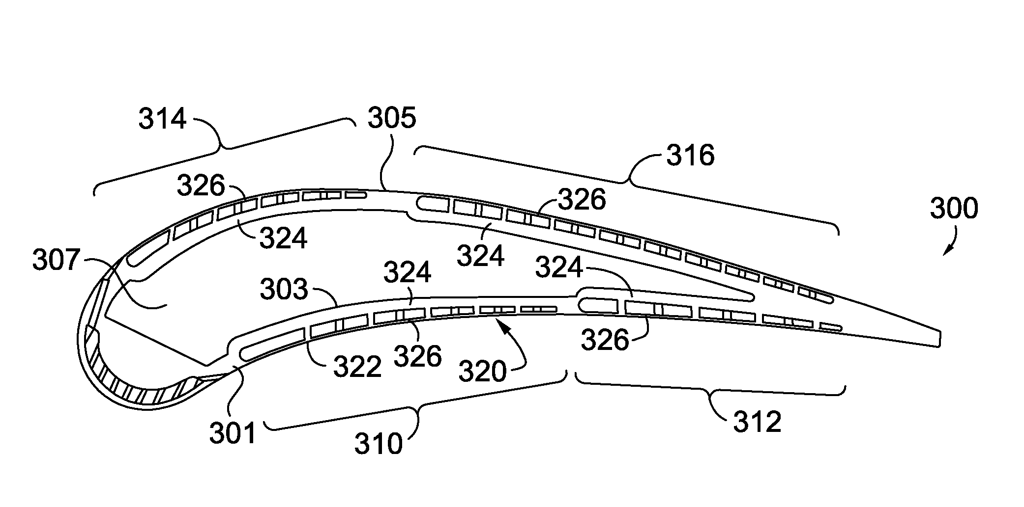
[0031]At a high level, the subject matter of this application generally relates to an airfoil for a gas turbine that includes cooling circuits integrated in various configurations. The airfoil may generally include an airfoil wall with an inner surface and an outer surface that at least partially encloses an airfoil chamber. Cooling circuits may be formed in various locations in the airfoil wall, to provide enhanced heat transfer from the airfoil when the gas turbine is in operation and cooling fluid or gas is passing through the cooling circuits. For turbine hardware operating in harsh environments, the use of this airfoil cooling technology is fully contemplated to be adapted to additional components such as outer and inner diameter platforms, blade outer or inner air shields, or alternative high temperature turbine components.

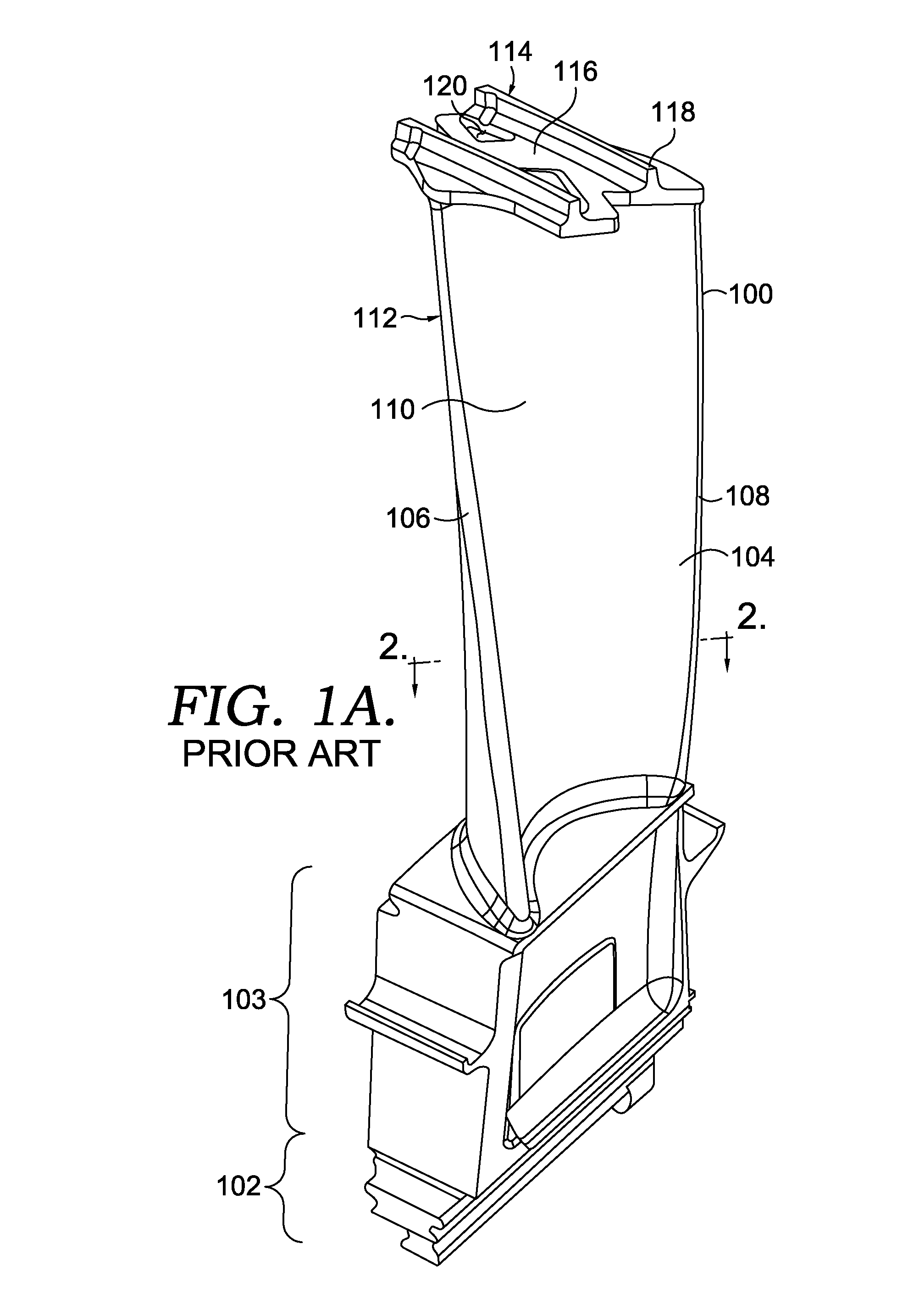
[0032]Referring now to FIG. 1A, a gas turbine blade 100 is provided. The turbine blade 100 comprises a bottom portion commonly referred to as a root 102, wh...


PUM

PropertyMeasurementUnit
distanceaaaaaaaaaa
pressureaaaaaaaaaa
axial lengthaaaaaaaaaa

Abstract

The present invention includes systems and methods for providing cooling channels located within walls of a turbine airfoil. These cooling channels include micro-circuits that taper in various directions along the length and width of the airfoil. In addition, these cooling channels have a variety of shapes and areas to facilitate convective heat transfer between the surrounding air and the airfoil.

Description

CROSS-REFERENCE TO RELATED APPLICATIONS[0001]This Application claims the benefit of U.S. Provisional Application No. 62 / 084,810, filed Nov. 26, 2014, and titled “GAS TURBINE AIRFOIL WITH TAPERED AIRFLOW MICRO CIRCUITS FOR IMPROVED COOLING,” which is incorporated herein by reference in its entirety. This application is also related by subject matter to concurrently filed U.S. patent application Ser. No. (not yet assigned; Attorney Docket No. PSSF.241854), filed Nov. 24, 2015, and titled “LEADING EDGE COOLING CHANNEL FOR AIRFOIL,” and concurrently filed U.S. patent application Ser. No. (not yet assigned; Attorney Docket No. PSSF.241855), filed Nov. 24, 2015, and titled “TAPERED COOLING CHANNEL FOR AIRFOIL.” The teachings of each of these concurrently filed applications are also incorporated herein by reference in their entirety.TECHNICAL FIELD[0002]The present invention relates to turbine airfoils, and more particularly, to cooling circuits incorporated into turbine airfoils.BACKGROUN...

Claims


Application Information

Patent Timeline
Patent Type & Authority Applications(United States)
IPC IPC(8): F01D5/18F01D9/04F01D25/12F01D5/14
CPCF01D5/187F01D5/147F01D9/041F01D25/12F05D2260/22141F05D2260/202F05D2240/12F05D2240/30F05D2230/31F05D2220/32F05D2250/182F05D2250/183F01D5/186F05D2240/303F05D2250/184F05D2260/204F05D2250/292B22F5/04Y02P10/25Y02T50/60B22F10/28
Inventor PIZANO, ELENA P.METTERNICH, JEREMYVOGEL, GREGORYKAWECKI, EDWIN J.
Owner ANSALDO ENERGIA IP UK LTD
Why Eureka
Try Eureka