Controller for variable valve mechanism

a variable valve and control mechanism technology, applied in the direction of electric control, machines/engines, output power, etc., can solve the problem of engine output fluctuation, and achieve the effect of reducing the number of engine output changes

Active Publication Date: 2016-05-26
TOYOTA JIDOSHA KK
View PDF1 Cites 32 Cited by
  • Summary
  • Abstract
  • Description
  • Claims
  • Application Information

AI Technical Summary

Benefits of technology

[0006]The apparatus disclosed in the above-mentioned Patent Document 1 reduces the lift amount of the intake valves to prevent increase in the engine output caused by increase in the number of operating cylinders due to reactivation from the cylinder deactivation mode. However, the torque fluctuation may occur due to other factors at reactivation from the cylinder deactivation mode.
[0008]Accordingly, it is an objective of the present invention to provide a controller for a variable valve actuation mechanism that reliably prevents torque fluctuation that may occur due to overlap in the opening duration of the intake valves between the cylinders at reactivation from the cylinder deactivation mode.Means for Solving the Problems
[0010]With this configuration, the control section executes the intake amount correction process. When the intake amount correction process is executed, the opening duration of the intake valve of the operating cylinders is temporarily increased at reactivation from the cylinder deactivation mode. This compensates for the intake air amount of the operating cylinder reduced by the flow of intake air into the reactivated cylinder. Thus, reduction in intake air in the operating cylinder, the intake valve of which have been opened and closed even during execution of the cylinder deactivation mode, is restrained immediately after reactivation from the cylinder deactivation mode, and reduction in the output torque of the operating cylinder is restrained. Consequently, at reactivation from the cylinder deactivation mode, torque fluctuation that may occur due to overlap in the opening duration of the intake valves between the cylinders is restrained in a reliable manner.
[0012]With this configuration, the control section executes the intake amount correction process. If overlap occurs in the opening duration of the intake valves between the cylinders by controlling the valve actuation on the basis of the engine output requirement at reactivation from the cylinder deactivation mode, execution of the intake amount correction process changes the valve actuation such that the intake air amount of the operating cylinder is increased as compared to a case in which the valve actuation is controlled on the basis of the engine output requirement during the cylinder deactivation mode. Thus, immediately after reactivation from the cylinder deactivation mode, reduction in the intake air in the operating cylinder is restrained, so that reduction in the output torque in the operating cylinder is restrained. As a result, torque fluctuation that may occur due to overlap in the opening duration of the intake valves between the cylinders is restrained in a reliable manner at reactivation from the cylinder deactivation mode.
[0018]The internal combustion engine, which includes a forced induction device, ensures the boost pressure during execution of the cylinder deactivation mode by exhaust gas pressure of the operating cylinder, the intake valve of which is opened and closed even during execution of the cylinder deactivation mode. If intake air also starts to flow into the reactivated cylinder due to reactivation from the cylinder deactivation mode, the intake air amount that flows into the operating cylinder is reduced by an amount corresponding to the intake air amount that flows into the reactivated cylinder. The reduction in intake air amount reduces the exhaust gas pressure of the operating cylinder and thus reduces the boost pressure. Since the reduction amount of the output torque when the intake air that flows into the operating cylinder is reduced in the internal combustion engine that includes the forced induction device is greater than a case with an internal combustion engine that does not include the forced induction device, the above-described torque fluctuation becomes significant. In this respect, the present configuration performs the above-described intake amount correction process to restrain reduction in intake air in the operating cylinder immediately after reactivation from the cylinder deactivation mode. This restrains the occurrence of torque fluctuation caused by reduction in the boost pressure immediately after reactivation from the cylinder deactivation mode.

Problems solved by technology

When the internal combustion engine is reactivated from a cylinder deactivation mode to an all cylinder operation mode, torque fluctuation tends to occur due to change in the engine output.

Method used


Image

  • Controller for variable valve mechanism
  • Controller for variable valve mechanism
  • Controller for variable valve mechanism

Examples


Embodiment Construction

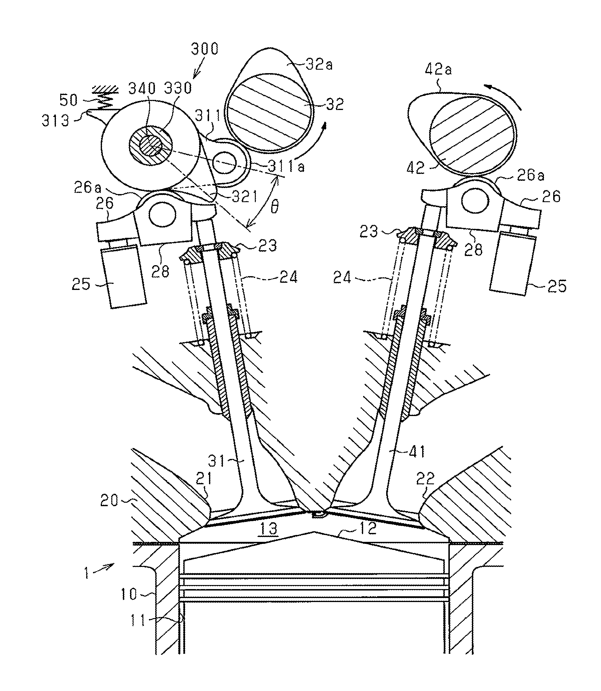
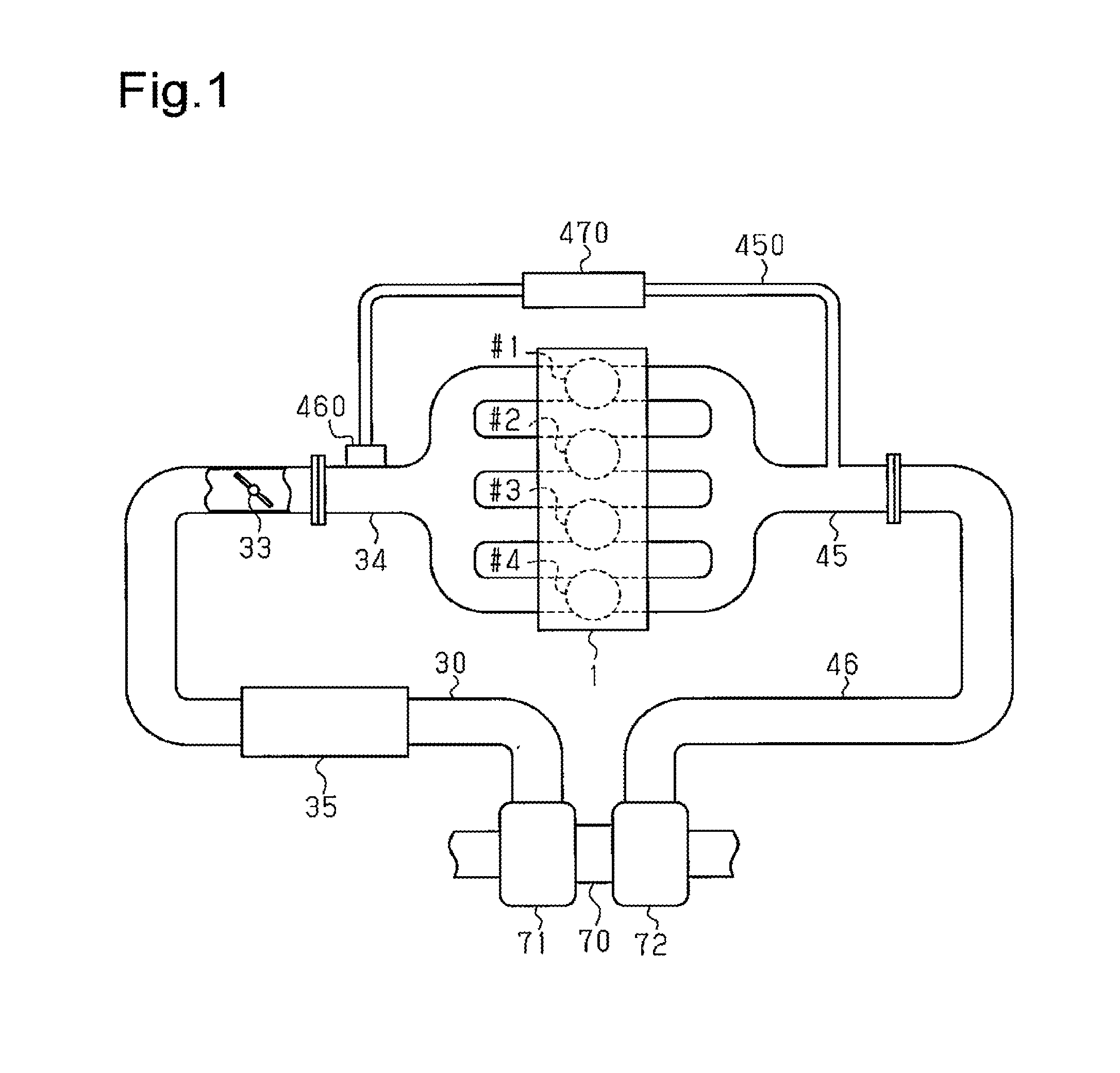
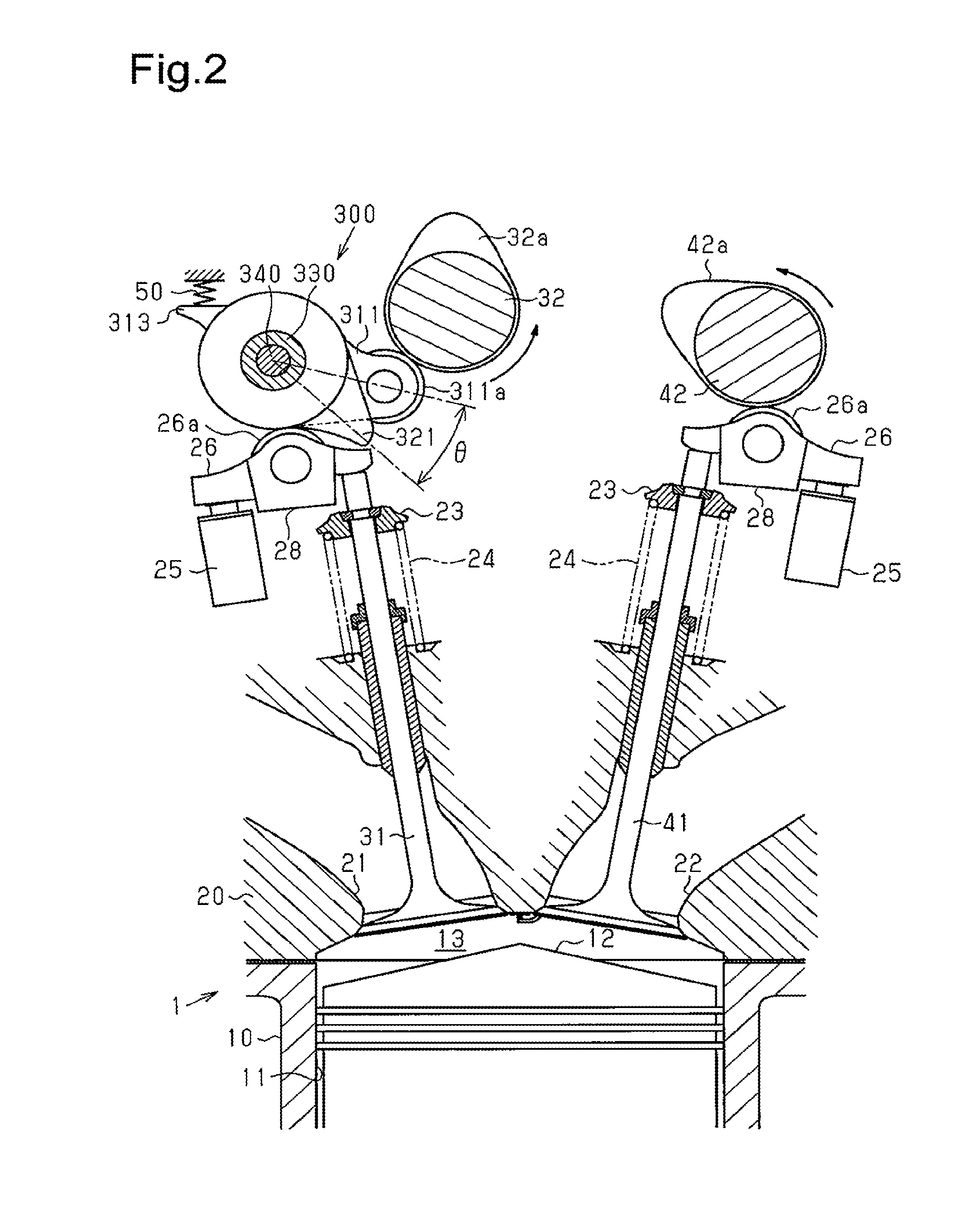
[0037]A controller for a variable valve actuation mechanism according to one embodiment applied to an inline four-cylinder engine will now be described with reference to FIGS. 1 to 11.

[0038]As shown in FIG. 1, an engine 1 includes four cylinders arranged in series, which are, a first cylinder #1, a second cylinder #2, a third cylinder #3, and a fourth cylinder #4.

[0039]The engine 1 also includes fuel injection valves, which inject fuel into the cylinders. Furthermore, an intake manifold 34, which introduces intake air into the cylinders, and an exhaust manifold 45, which discharges exhaust gas from the cylinders, are connected to the engine 1.

[0040]The intake manifold 34 is connected to an intake passage 30. A throttle valve 33, which regulates the intake air amount, is located in the intake passage 30.

[0041]The exhaust manifold 45 is connected to an exhaust passage 46.

[0042]The engine 1 includes a forced induction device for increasing the pressure of intake air using exhaust gas. ...


PUM


Abstract

An internal combustion engine is provided with a plurality of cylinders, air intake valves provided to each of the cylinders, and a variable valve actuation mechanism for varying the valve actuation of the air intake valves. A motor drives the variable valve actuation mechanism. A motor controller controls the motor. The internal combustion engine is capable of operating in a cylinder deactivation mode, in which the air intake valves of some of the cylinders are kept shut. When the internal combustion engine is reactivated from the cylinder deactivation mode, the motor controller executes an air intake amount correction process, in which the opening duration of the air intake valves is temporarily increased, thereby increasing the amount of air taken in by operating cylinder for which the air intake valves have been opened or closed even during the cylinder deactivation mode.

Description

TECHNICAL FIELD[0001]The present invention relates to a controller for a variable valve actuation mechanism.BACKGROUND ART[0002]Internal combustion engines that use cylinder deactivation during engine operation have been proposed. Cylinder deactivation shuts down some of the cylinders by stopping opening and closing operation of the intake valves to keep the valves closed for some of the cylinders.[0003]When the internal combustion engine is reactivated from a cylinder deactivation mode to an all cylinder operation mode, torque fluctuation tends to occur due to change in the engine output.[0004]For this reason, for example, the internal combustion engine disclosed in Patent Document 1 reduces the lift amount of the intake valves when the engine is reactivated from the cylinder deactivation mode to reduce the engine output. This configuration restrains the occurrence of torque fluctuation caused by increase in the engine output when the engine is reactivated from the cylinder deactiv...

Claims


Application Information

Patent Timeline
Patent Type & Authority Applications(United States)
IPC IPC(8): F02D13/02F02D13/06F02B29/02F02D41/00
CPCF02D13/023F02B29/02F02D13/06F02D41/0047F01L1/185F01L1/2405F01L1/267F01L13/0063F01L2820/032F02D41/0002F02D41/008F02D41/0087F02D2041/001F02D2041/0012F02D2250/21F02M26/05F02M26/23F01L2305/00Y02T10/12Y02T10/40
Inventor KAWAGUCHI, YOHEI
Owner TOYOTA JIDOSHA KK
Why Eureka
Try Eureka