Correction of imaging methods in a magnetic resonance device

Inactive Publication Date: 2016-05-26
SIEMENS HEALTHCARE GMBH
View PDF6 Cites 6 Cited by
  • Summary
  • Abstract
  • Description
  • Claims
  • Application Information

AI Technical Summary

Benefits of technology

[0053]In the event of an imaging technology that (e.g., by an inversion pulse) also involves a phase position of the spins, it is an embodiment that the interpolation is based not on the “magnitude images” composed from the absolutes values of signal amplitudes but on (“phased”) images provided with information relating to the phase position. This yields the advantage that information relating to a zero transition of the signal intensity is not lost and thus an even more precise interpolation is made possible. For this purpose it may be advantageous that—if possible—a sign-sensitive and/or phase-sensitive interpolation is carried out.
[0054]It is also an embodiment that in addition to or as an alternative to the method described above, a receive B1 correction is carried out in order to correct receive-side inhomogeneities. Differing signal inte

Problems solved by technology

As a result, the images generated are not homogeneous but exhibit signal differences even in the case of effectively identical tissue.
This is an undesirable effect since a diagnosis may be based on the comparison of spatially separate but identical tissues, for example, between a left side and a right side of a head.
The use of two channels, however, does not under certain circumstances adequately reduce the problem of the location-dependent changes in contrast produced by the dielectric resonances.
A greater number of channels is, however, complicated and technical implementation may be achieved only with difficulty.
An alternative is to use B1-insensitive radio-frequency (“RF”) pulses, but this requires more time in order to carry out a measurement.
Furthermore, this method tends to introduce more energy into the patient, for which reason it may, as a general rule, on

Method used


Image

  • Correction of imaging methods in a magnetic resonance device
  • Correction of imaging methods in a magnetic resonance device
  • Correction of imaging methods in a magnetic resonance device

Examples


Embodiment Construction

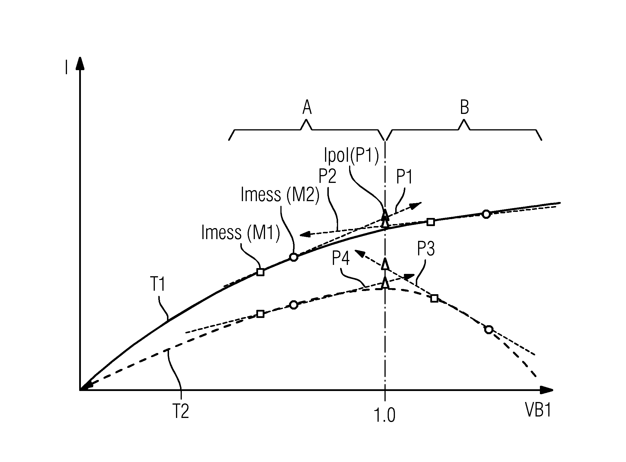
[0072]FIG. 1 depicts a signal intensity or signal strength I in arbitrary units of pixels of two MR measurements or MR images M1 and M2 plotted against a ratio VB1 of an actual transmit B1 value at the location of a respective pixel to a transmit B1 target value. The ratio also corresponds to a ratio of a correspondingly arising actual flip angle to a target flip angle. The MR images M1 and M2 differ from one another by virtue of differing transmitter settings, in particular, for differing transmitter scalings. The signal intensities measured in this situation are dependent on the local transmit B1 values for M1 and for M2.

[0073]To the left of the ratio VB1=1, in other words where VB1 value is too low in a spatial region A of the object to be measured. Conversely, to the right of the ratio VB1=1, in other words where VB>1, the actual transmit B1 value is too high in another spatial region A of the object to be measured.

[0074]The ratio VB1 is given by the transmitter scaling multipli...


PUM


Abstract

In a method, by a magnetic resonance device, a transmit B1 field map is determined for a region, a plurality of MR images of at least one part of the region are acquired using transmitter settings differing from each other, and signal intensities of individual pixels measured by the MR images are interpolated by the transmit B1 field map. A correction of the signal intensities may also be effected by carrying out a receive B1 correction by a spatial mirroring of the transmit B1 field map on a symmetry plane of a measured object. A magnetic resonance device is used to carry out the method. The method may be applied, for example, in medical diagnostics.

Description

[0001]This application claims the benefit of DE 10 2014 223 734.3, filed on Nov. 20, 2014, which is hereby incorporated by reference in its entirety.TECHNICAL FIELD[0002]The embodiments relate to a method used to determine a transmit B1 field map for a region by a magnetic resonance device. The embodiments may be applied in medical diagnostics, for example, for magnetic resonance examinations in the medical field, (e.g., for measurements on a head).BACKGROUND[0003]When magnetic resonance (“MR”) examinations are carried out on a person, dielectric resonances cause a considerable spatial inhomogeneity in the transmit (“TX”) B1 field and the receive (“RX”) B1 field, above all in the case of field strengths in excess of two Tesla. As a result, the images generated are not homogeneous but exhibit signal differences even in the case of effectively identical tissue. This is an undesirable effect since a diagnosis may be based on the comparison of spatially separate but identical tissues, f...

Claims


Application Information

Patent Timeline
IPC IPC(8): G01R33/24G06T7/00G06T3/40G01R33/565
CPCG01R33/246G01R33/5659G06T2207/10088G06T3/4007G06T7/0038
Inventor KOHLER, MICHAELLANDSCHUTZ, WILFRIEDNISTLER, JURGENVESTER, MARKUS
Owner SIEMENS HEALTHCARE GMBH
Why Eureka
Try Eureka