Integrator and Touch Sensing System Using the Same

a technology of integrated sensors and touch sensors, applied in the field of integration sensors, can solve the problems of limited number of integrations, achieve the effects of wide output voltage range, reduce circuit area, and increase the number of integrations

Active Publication Date: 2016-05-26
LG DISPLAY CO LTD
View PDF1 Cites 15 Cited by
  • Summary
  • Abstract
  • Description
  • Claims
  • Application Information

AI Technical Summary

Benefits of technology

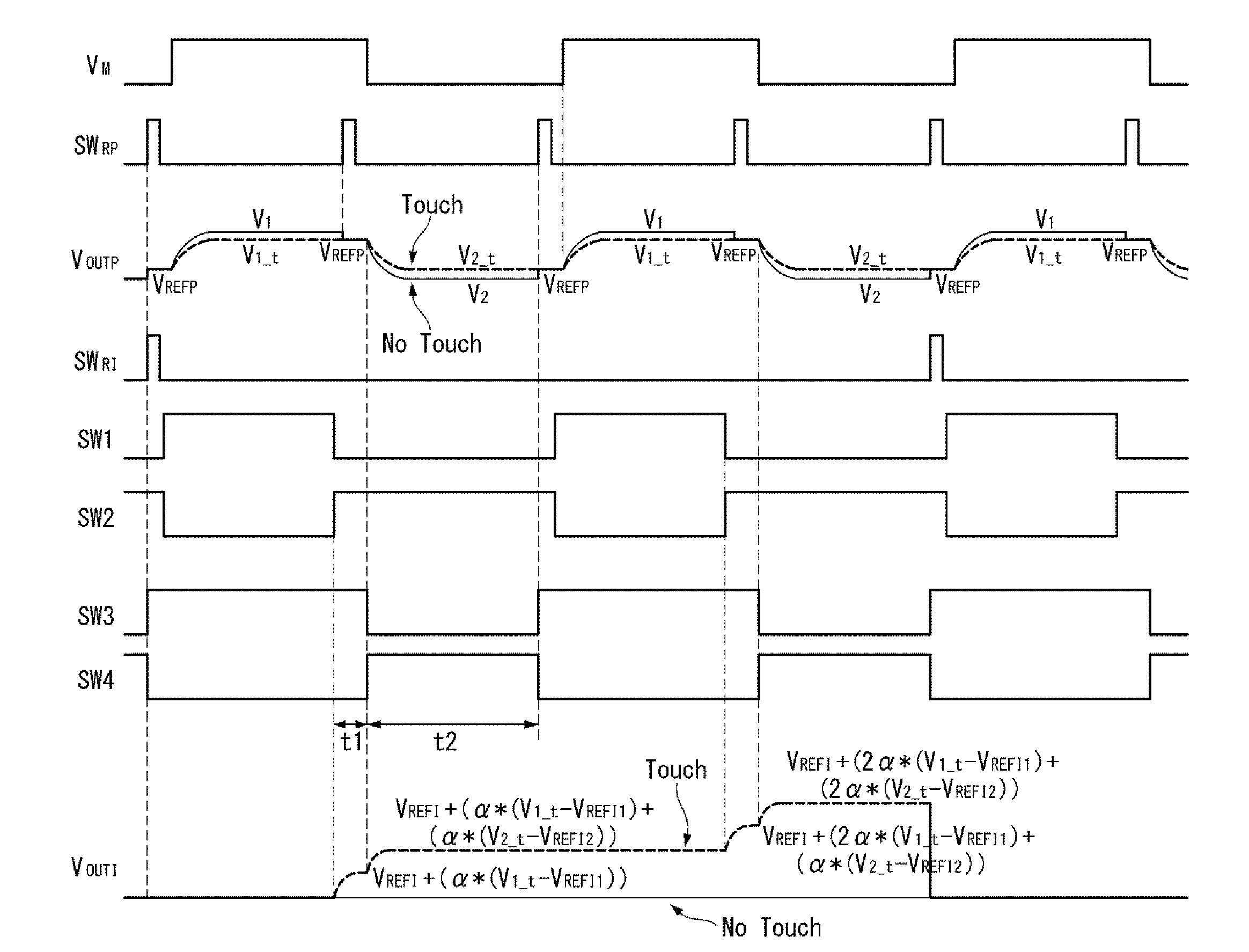
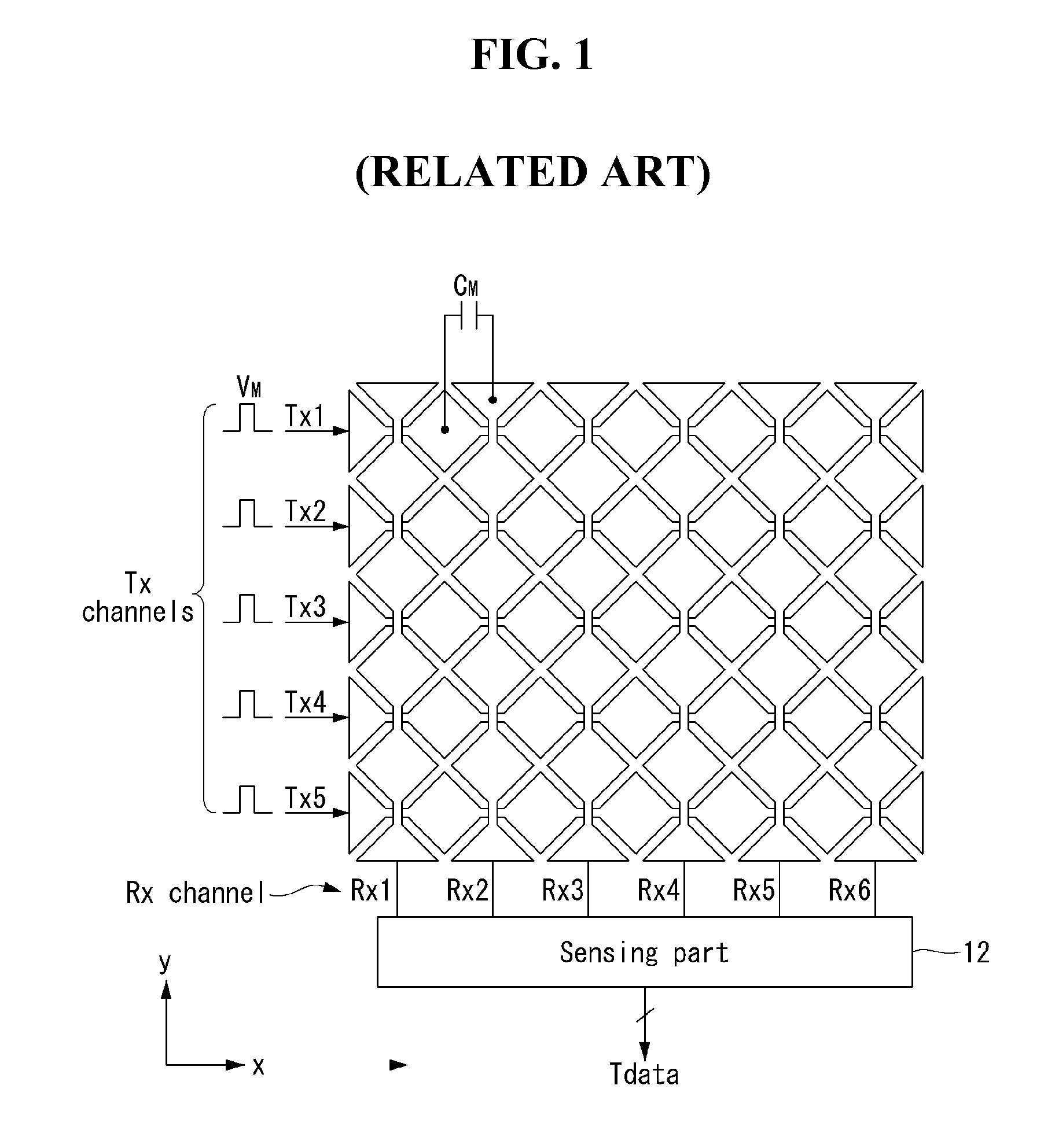
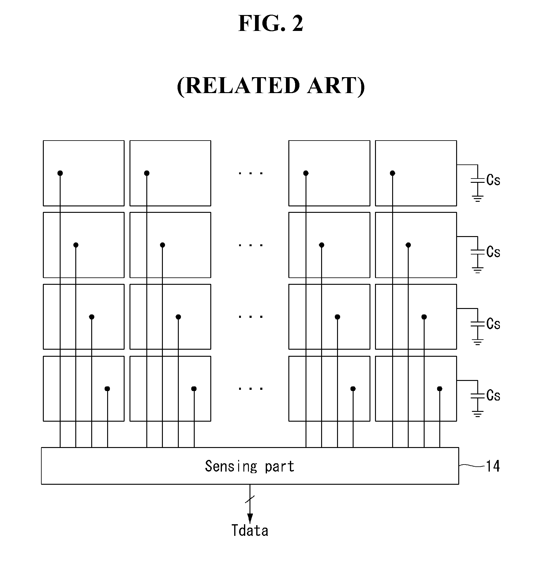
[0015]An aspect of this document is to provide an integrator which allows for a wider output voltage range, an increased number of integrations, and a reduction in the circuit area needed for a double-sampling integrator circuit, a touch sense circuit using the same, and a display device coupled with the touch sensing system, and a method of detecting touch input using such touch sense circuit.

Problems solved by technology

First, the number of integrations is limited because the voltage of the charge amplifier, which is integrated by the integrator, is higher than necessary. In an example shown in FIG. 3, a touch can be detected based only on the difference |V1−V1_t| between a non-touch voltage V1 and a touch voltage V1_t; however, the integrator integrates a voltage higher than necessary since the output voltage Vout of the charge amplifier is higher than the voltage difference |V1−V1_t|. The output voltage Vout of the charge amplifier is V1 when there is no touch, and V1_t when there is touch input. In FIG. 3, Vref is the reference voltage of the charge amplifier.
Second, the integrator has a larger circuit area when it is made capable of double sampling. The integrator may be implemented as a single-ended amplifier or a differential amplifier. The integrator may be implemented as a differential type Then, the integrator accumulates the sampled voltage in a capacitor CFBI and integrates it. integrator capable of double sampling. This differential type integrator requires more than twice as many integrators and switches as the single-ended integrator.
Third, the output voltage range of the integrator is narrow. The output voltage of the integrator ranges from 0 to VDD / 2, where VDD is the supply voltage of the integrator, because the reference voltage of the integrator is VDD / 2.

Method used


Image

  • Integrator and Touch Sensing System Using the Same
  • Integrator and Touch Sensing System Using the Same
  • Integrator and Touch Sensing System Using the Same

Examples


Embodiment Construction

[0031]A display device according to embodiments herein may be implemented as a flat panel display such as a liquid crystal display (LCD), a field emission display (FED), a plasma display panel (PDP), an organic light emitting display (OLED), or an electrophoresis display (EPD). Although the following exemplary embodiments will be described with respect to a liquid crystal display as an example of the flat plane display, it is to be noted that the display device of this invention is not limited to the liquid crystal display.

[0032]Hereinafter, exemplary embodiments of the present invention will be described in detail with reference to the accompanying drawings. Like reference numerals refer to like elements throughout the specification. In the following description, detailed descriptions of well-known functions or configurations will be omitted where they may unnecessarily obscure the subject matters of the invention.

[0033]FIG. 4 is a view showing a touch sensing system according to t...


PUM


Abstract

A touch sense circuit comprises a first sampling circuit to sample a touch sense signal during a first period of a touch drive signal in which the touch drive signal is at a first level, to generate a first sampled signal; a second sampling circuit to sample the touch sense signal during a second period of the touch drive signal in which the touch drive signal is at a second level, to generate a second sampled signal, the second sampled signal in a same polarity as the first sampled signal; and an integrator including an input terminal and an output terminal, both the first sampled signal and the second sampled signal being input to the input terminal of the integrator and integrated to generate an output signal at the output terminal of the integrator, the output signal being used to detect a touch input.

Description

CROSS-REFERENCE TO RELATED APPLICATION[0001]This patent application claims priority under 35 U.S.C. §119(a) from Republic of Korea patent application no. 10-2014-0163414 filed on Nov. 21, 2014, which is incorporated by reference herein in its entirety.BACKGROUND[0002]1. Field[0003]The present disclosure relates to an integrator, a touch sensing system using the same, and a display device coupled with the touch sensing system.[0004]2. Related Art[0005]User interfaces (UI) enable humans (users) to interact with various types of electric or electronic devices so that they can easily control the devices as they want. Typical examples of the user interfaces include keypads, keyboards, mice, on-screen displays (OSD), and remote controllers with an infrared communication capability or radio frequency (RF) communication capability. The user interface technology is continuing to make progress toward higher user sensitivity and ease of operation. Recently, user interfaces have been evolving i...

Claims


Application Information

Patent Timeline
Patent Type & Authority Applications(United States)
IPC IPC(8): G06F3/041G09G3/36
CPCG06F3/0416G09G3/3696G06F3/0412G06F3/044G06F3/04166G06F3/041G06G7/186
Inventor KIM, BEOMJINLEE, DUKHYO
Owner LG DISPLAY CO LTD
Why Eureka
Try Eureka