
Multi-tenancy via code encapsulated in server requests

a server request and multi-tenancy technology, applied in the field of multi-tenancy via code encapsulation in server requests, can solve the problems of large high cost of hosting an application, and high cost of physical machine provisioning and allocation,

Active Publication Date: 2016-05-26
AUTH0
View PDF8 Cites 51 Cited by
  • Summary
  • Abstract
  • Description
  • Claims
  • Application Information

AI Technical Summary

Benefits of technology

The patent text describes a method and system for running computer code in a secure multi-tenant environment. This approach involves creating containers specifically for the code, and managing the resource costs associated with running the code. The system also allows for the code to be shared across multiple applications, reducing costs and improving application density. The technical effects of this approach include maximizing application density by sharing resource costs and managing resource use at a thread level, as well as providing a secure and flexible way to manage multi-tenant applications on a cloud computing platform.

Problems solved by technology

Thus, much effort is typically spent just on the logistics of managing the backend.
Specifically, hosting an application has resource costs such as memory and CPU.
The cost to provision and allocate a physical machine is greater than the cost to provision and allocate a virtual machine.
In turn, the cost to provision and allocate a virtual machine is greater than the cost to provision and allocate a multi-tenant container.
Finally, the cost to execute a process in a containers in turn is more expensive than the cost to execute a thread.
However, while operating systems allow processes to manage resources, they do not provide adequate functionality to manage resources at the thread level.
For example, known PaaS platforms may not provide an attractive cost structure and may run on an asynchronous programming model, requiring polling for the results of the computation, which adversely affects latency.
However, such approach includes security risks in that the code is managed elsewhere, making it vulnerable to copying or being hacked.
Execution time may be limited to the typical lifetime of an HTTP request.
Docker merely abstracts away environment, but does not provide multi-tenancy.

Method used


Image

  • Multi-tenancy via code encapsulated in server requests
  • Multi-tenancy via code encapsulated in server requests
  • Multi-tenancy via code encapsulated in server requests

Examples


example functional

Blocks

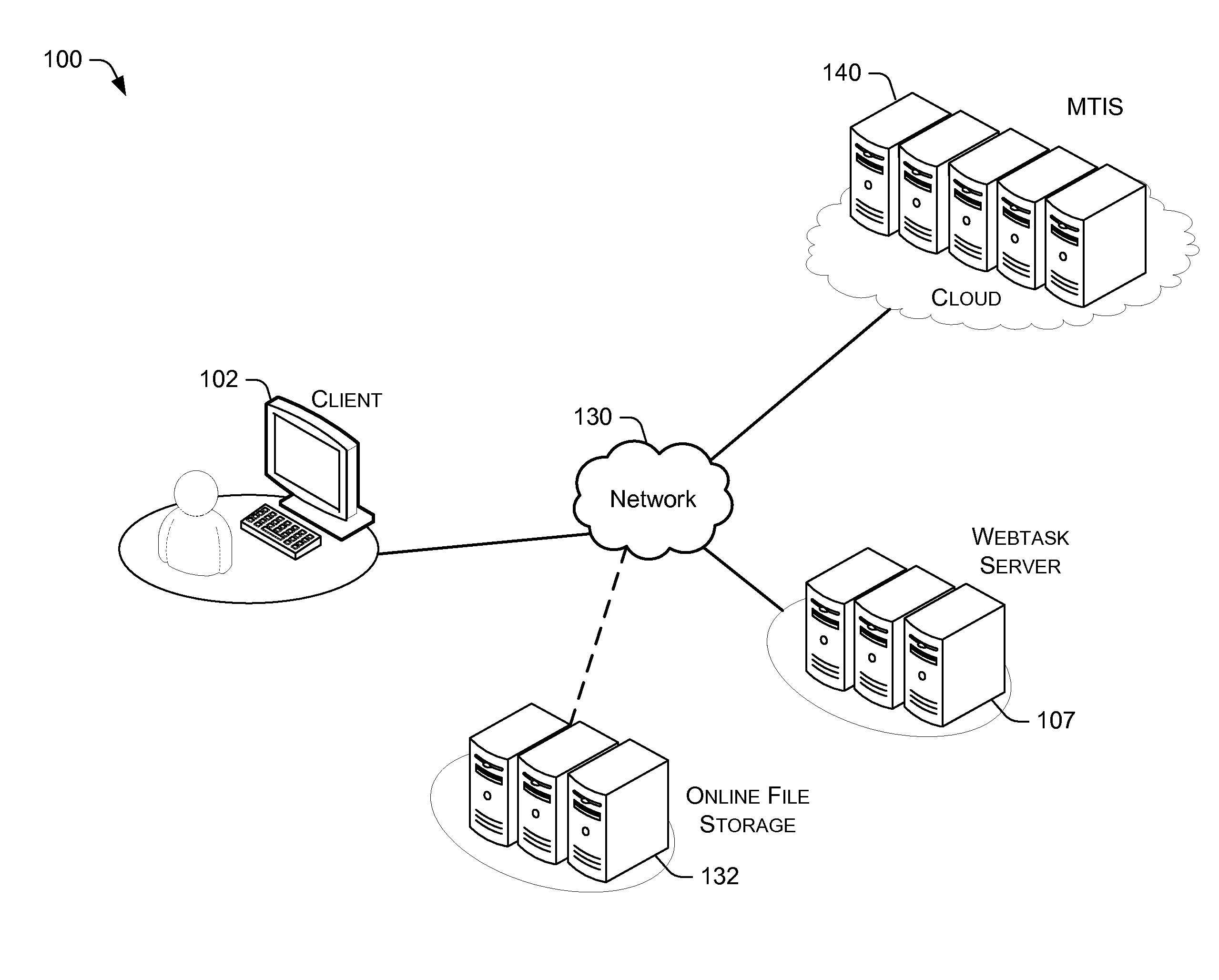
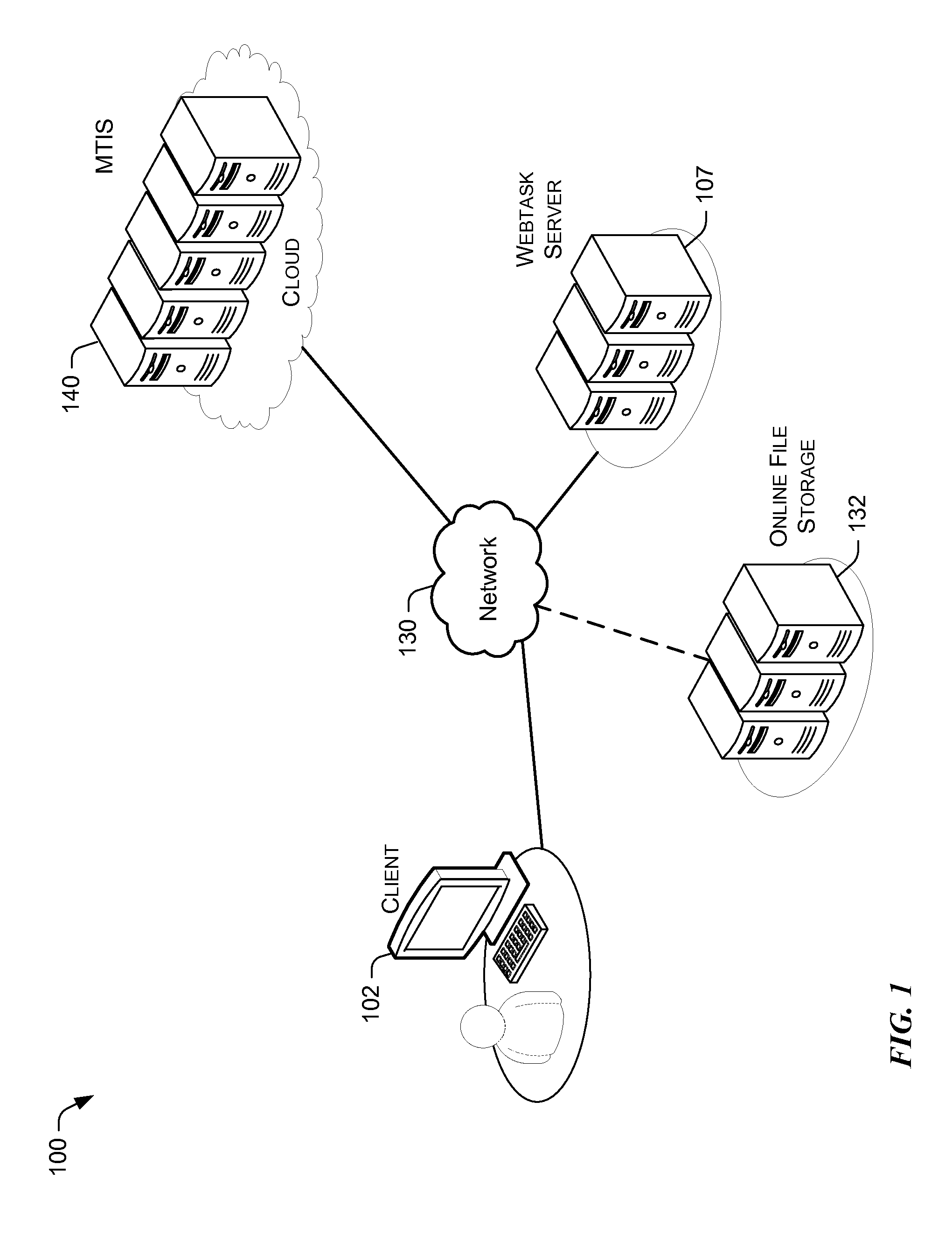
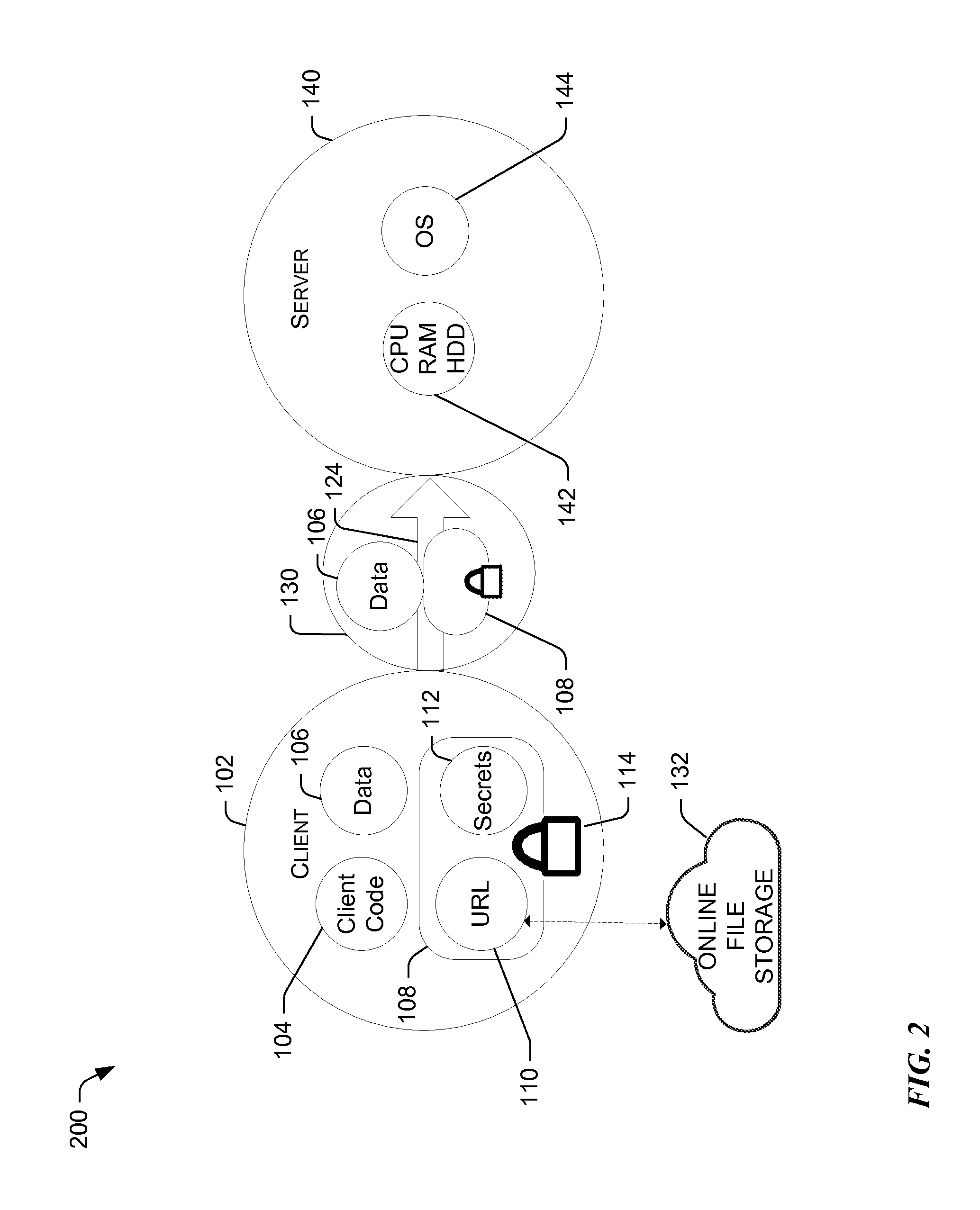
[0022]Reference now is made to FIG. 2, which illustrates a block diagram of the data framework for executing code (e.g., a computer routine) in multi-tenant containers. System 100 illustrates a client 102 communicating with a server 104 via a network 130.

[0023]The server 140 may operate on a cloud and include raw computing resources 142, such as CPU, memory, disk, etc., as well as an operating system 144. Thus, server 140 provides raw computing resources 142 and an operating system, which can be viewed as a cloud commodity. Server 140 provides the backend for an application in the form of a computer routine to be run. What is notably missing from the server 140 is server code that implements part of the application logic as well as secrets this code requires to access protected data or functionality, such as database connection strings, API keys, etc. Both server code and the secrets are data that are serialized together into one bundle 108 and can now be found in the client 1...

example call

Flow Process

[0051]With the foregoing overview of the multi-tenancy via code encapsulated in server requests system, it may be helpful now to consider a high-level discussion of example call flow processes. To that end, FIG. 4 illustrates a high level example call flow process for executing a code (e.g., computer routine) in a multi-tenant infrastructure environment, wherein the executed computer routine is non-persistent. The call flow process 400 is illustrated as a collection of steps in a logical call flow, which represents a sequence of operations that can be implemented in hardware, software, or a combination thereof. In the context of software, the steps represent computer-executable instructions that, when executed by one or more processors, perform the recited operations. Generally, computer-executable instructions may include routines, programs, objects, components, data structures, and the like that perform particular functions or implement particular abstract data types. ...

example use cases

[0062]With the foregoing explanation of the system and method of encapsulating computer routine in a server request, it may be helpful to provide a high level discussion of some example use cases. The concepts and system discussed herein can be applied to various use cases. For example, they may be applied to distributed applications, where an application may be architected into separate components, each designed to operate independently of others. Those separate components can send the computer routine to be executed via the MTIS 140 to different instances.

[0063]In on example, the system described herein can be used for offloading. To that end, an application may execute a routine either locally or remotely using the MTIS 140. In situations where the local computing resources are not available or are insufficient, the application may offload computing requests to the cloud via the MTIS 140.

[0064]In one example, the concepts discussed herein can be used for scripting WEB services. A...


PUM


Abstract

A multitenant infrastructure server (MTIS) is configured to provide an environment to execute a computer routine of an arbitrary application. The MTIS receives a request from a webtask server to execute the computer routine in a webtask container. The computer routine is executed in the webtask container at the MTIS. Upon successful execution of the computer routine, a result set is returned to the webtask server. If the execution of the computer routine is unsuccessful, an error notification is returned to the webtask server. The resources consumed during the execution of the computer routine are determined. The webtask container is destroyed to prevent persistent storage of the computer routine on the MTIS.

Description

CROSS-REFERENCES TO RELATED APPLICATIONS[0001]The present application claims the benefit of priority under 35 U.S.C. §119 from U.S. Provisional Patent Application Ser. No. 62 / 084,511, entitled “Multi-Tenancy Via Code Encapsulated In Server Requests,” filed on Nov. 25, 2014, which is hereby incorporated by reference in its entirety for all purposes.BACKGROUND[0002]Computer application architectures have trended towards distributing different computing functions across multiple computers. Indeed, a majority of modern mobile and web applications are based on a distributed architecture. For example, in a client-server architecture, the split of application functionality between the front end and the backend helps reuse backend computing resources across several clients. It also creates a trust boundary between the client and the server, which enables servers to authorize access to protect data or functionality. In a typical client-server application, the client submits data for processi...

Claims


Application Information

Patent Timeline
Patent Type & Authority Applications(United States)
IPC IPC(8): H04L29/06H04L29/08
CPCH04L67/1097H04L67/40H04L67/34H04L67/025G06F9/547G06F2209/549H04L67/561H04L67/133G06F21/53H04L67/02G06F16/955G06F8/433G06F21/604
Inventor JANCZUK, TOMASZWOLOSKI, MATIAS
Owner AUTH0
Learn More