Control Method For Synchronized Fabric Circulation In Conveyor Drive Fabric Dyeing Machine

a conveyor drive and fabric dyeing machine technology, applied in computer control, liquid/gas/vapor roped fabric treatment, instruments, etc., can solve the problems of poor machine operation, entanglement or jamming of fabric, and general time-consuming adjustment for synchronization, so as to facilitate the flow and conveyance of fabric smooth, the effect of automatizing the operation of the machine and simplifying the operation

Active Publication Date: 2016-06-02
CHANG
View PDF4 Cites 4 Cited by
  • Summary
  • Abstract
  • Description
  • Claims
  • Application Information

AI Technical Summary

Benefits of technology

[0007]An advantage of the present invention is that it is not necessary to fix the length of fabric to be dyed and, regardless the length and weight of the fabric, the computer or PLC control unit performs automatic computation and controls the fabric g

Problems solved by technology

In other words, the two must be operated in a synchronous manner, otherwise fabric entangling or jamming may result.
Practically, the length or weight of fabric for each dyeing batc

Method used


Image

  • Control Method For Synchronized Fabric Circulation In Conveyor Drive Fabric Dyeing Machine
  • Control Method For Synchronized Fabric Circulation In Conveyor Drive Fabric Dyeing Machine
  • Control Method For Synchronized Fabric Circulation In Conveyor Drive Fabric Dyeing Machine

Examples


Embodiment Construction

[0012]The following descriptions are exemplary embodiments only, and are not intended to limit the scope, applicability or configuration of the invention in any way. Rather, the following description provides a convenient illustration for implementing exemplary embodiments of the invention. Various changes to the described embodiments may be made in the function and arrangement of the elements described without departing from the scope of the invention as set forth in the appended claims.

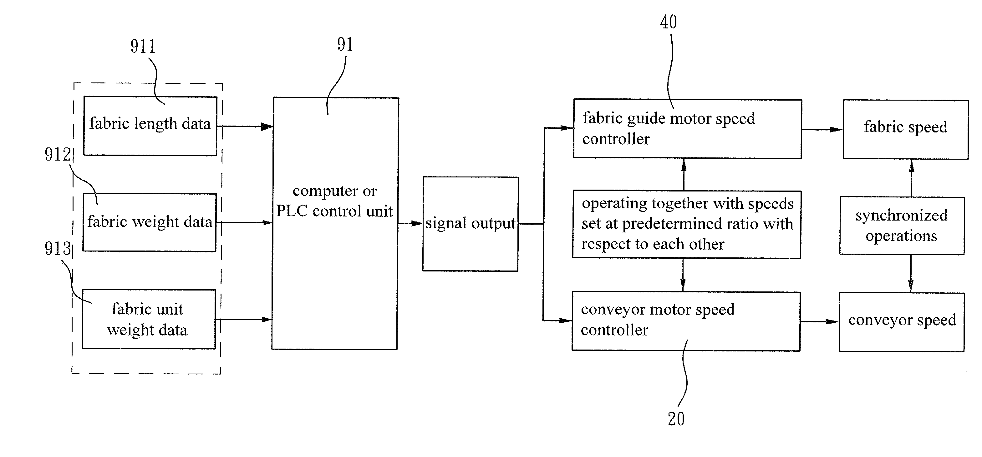
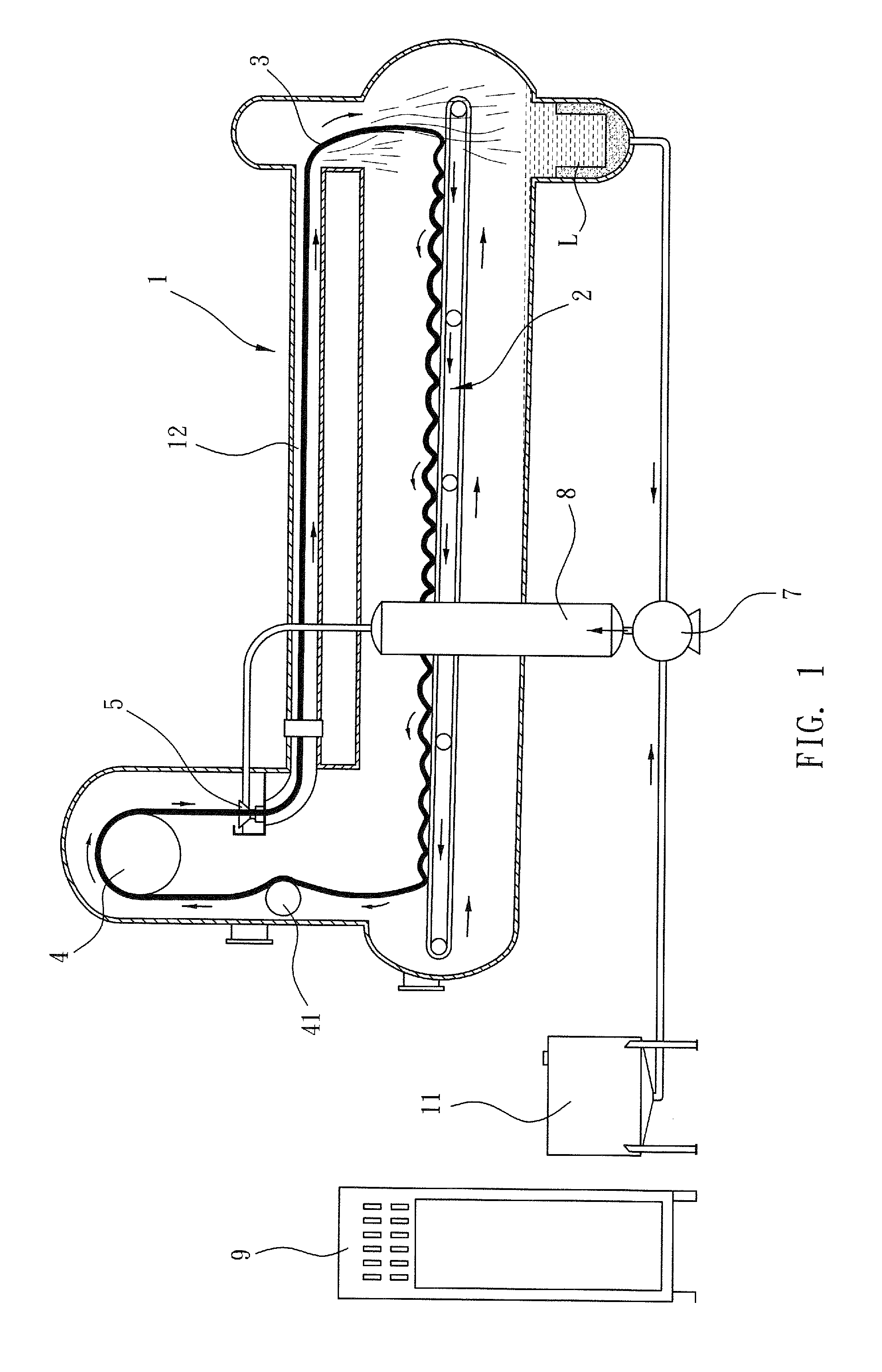
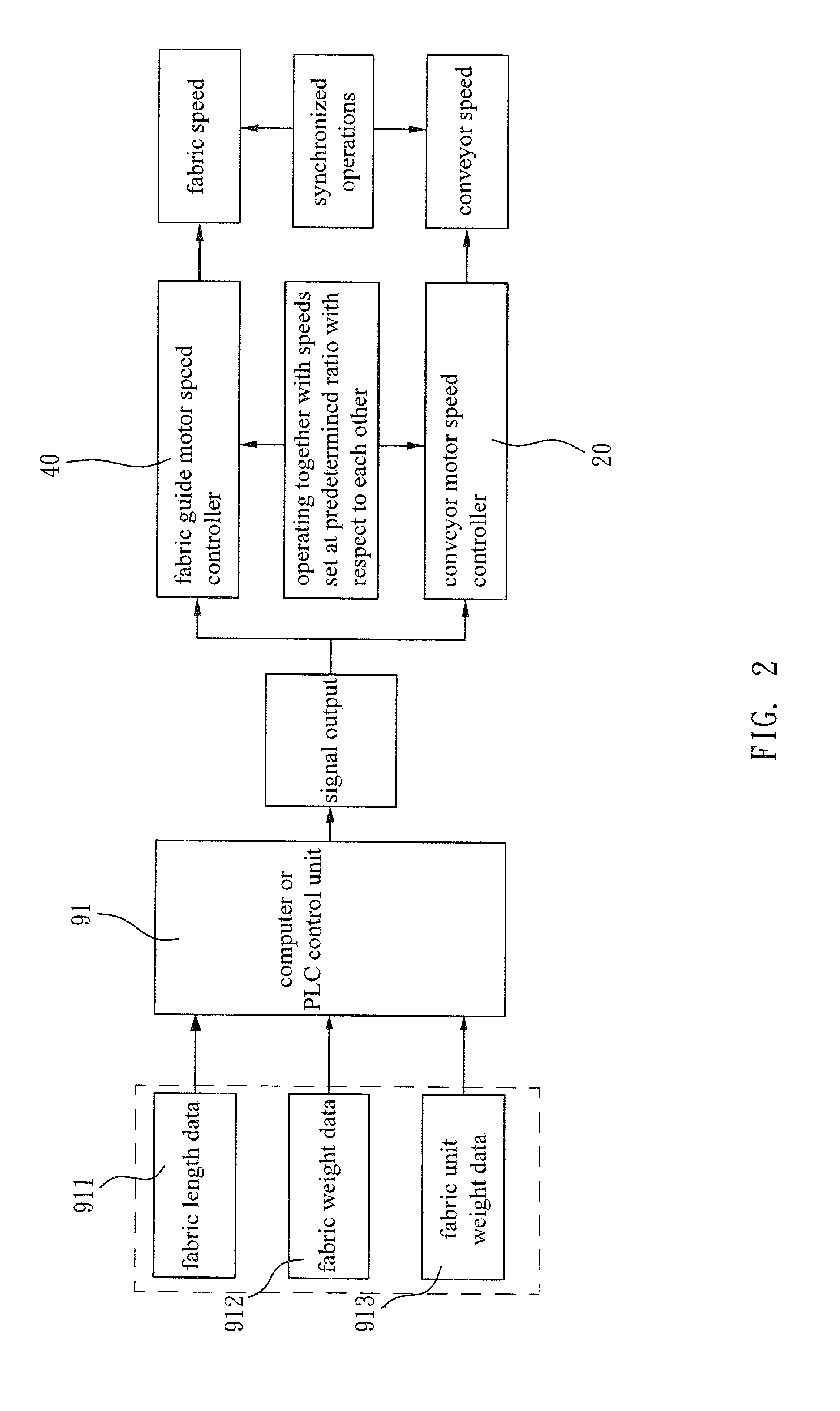
[0013]The present invention provides a control method that is applicable to a fabric dyeing machine shown in FIG. 1. The fabric dyeing machine comprises a machine body 1 in which a dyeing tube 12, a fabric guide 4, and a conveyor 2 are arranged. The fabric guide 4 is driven to rotate by a fabric guide motor (not shown). The conveyor 2 is driven and operated by a conveyor motor (not shown). Fabric 3 moves around the fabric guide 4 and passes through a nozzle 5 to enter the dyeing tube 12 and then fal...


PUM


Abstract

Disclosed is a control method for synchronized fabric circulation in a conveyer drive fabric dyeing machine. During a dyeing process of fabric, the fabric is driven by a fabric guide to move in a circulating manner and the time period for a cycle of circulation is set in consistency with the time period that a conveyor moving from a rear end to a front end so as to achieve synchronization that makes the circulation smooth. The control method is performed with a computer or a PLC control unit that is supplied with fabric length data or fabric weight data and fabric unit weight data and, based on such data, performs an automatic operation of computation and supply of a signal to speed controllers of the fabric guide motor and the conveyor motor to set the speeds thereof at a predetermined ratio with respect to each other for synchronized operations.

Description

(a) TECHNICAL FIELD OF THE INVENTION[0001]The present invention generally relates to a conveyor drive fabric dyeing machine that is used to dye rope-like fabric, and more particularly to a control method for achieving operation synchronization of fabric and a fabric guide and a conveyor.(b) DESCRIPTION OF THE PRIOR ART[0002]FIG. 1 shows a structure of a conveyor drive fabric dyeing machine, which comprises a machine body 1 in which a dyeing tube 12, a fabric guide 4, and a conveyor 2 are arranged. The fabric guide 4 is driven to rotate by a fabric guide motor (not shown). The conveyor 2 is driven and operated by a conveyor motor (not shown).[0003]The principle of operation is as follows. Fabric 3 moves around the fabric guide 4 and passes through a nozzle 5 to enter the dyeing tube 12 and then falls onto the conveyor 2 to complete a cycle of circulation. Dye liquid L is pressurized by a pump 7 to flow through a heat exchanger 8 (for heating or cooling) to enter the nozzle 5 for gene...

Claims


Application Information

Patent Timeline
IPC IPC(8): D06B3/36G05B15/02D06B3/24
CPCD06B3/36G05B15/02D06B3/24B32B5/00C14B7/00D06B3/28
Inventor CHANG
Owner CHANG
Why Eureka
Try Eureka