A high speed switch reluctance motor on a turbocharger

a technology of high-speed switch and reluctance motor, which is applied in the direction of magnetic circuit rotating parts, piston pumps, magnetic circuit shape/form/construction, etc., can solve the problems of turbo lag, difficult to retain the rotor on the turbocharger shaft, and difficult to retain the rotor in the desired orientation

Active Publication Date: 2016-06-02
BORGWARNER INC
View PDF7 Cites 1 Cited by
  • Summary
  • Abstract
  • Description
  • Claims
  • Application Information

AI Technical Summary

Benefits of technology

[0013]A turbocharger includes a switched reluctance motor to address turbolag. Due to the high speeds required (e.g., 100,000 rpm) and the low strength electrical steel used in switched reluctance motors designed for turbocharger applications, it is very difficult to retain the rotor on the turbocharger shaft and to retain the rotor in a desired orientation. To address these concerns, the turbocharger includes a switched reluctance motor. The motor includes a rotor assembly having magnetic laminated elements that are mounted on the shaft, and are held in place by nonmetallic nonconductive pins. In addition, the pins transmit the motion of the laminated elements to the shaft. By arranging the pins on opposing sides of the shaft, the motor torque is transmitted to the shaft, orientation of the laminated elements relative to the shaft is locked, balance of the rotor assembly is minimally affected, and the set of laminated elements is free to grow axially as necessary during operation of the turbocharger. In addition, it is possible to balance the rotor assembly prior to installation into the turbocharger.

Problems solved by technology

This performance delay is known as turbo lag.
Due to the high speeds required (e.g., 100,000 rpm) and the low strength electrical steel used in switched reluctance motors designed for turbocharger applications, it is very difficult to retain the rotor on the turbocharger shaft and to retain the rotor in a desired orientation.

Method used


Image

  • A high speed switch reluctance motor on a turbocharger
  • A high speed switch reluctance motor on a turbocharger
  • A high speed switch reluctance motor on a turbocharger

Examples


Embodiment Construction

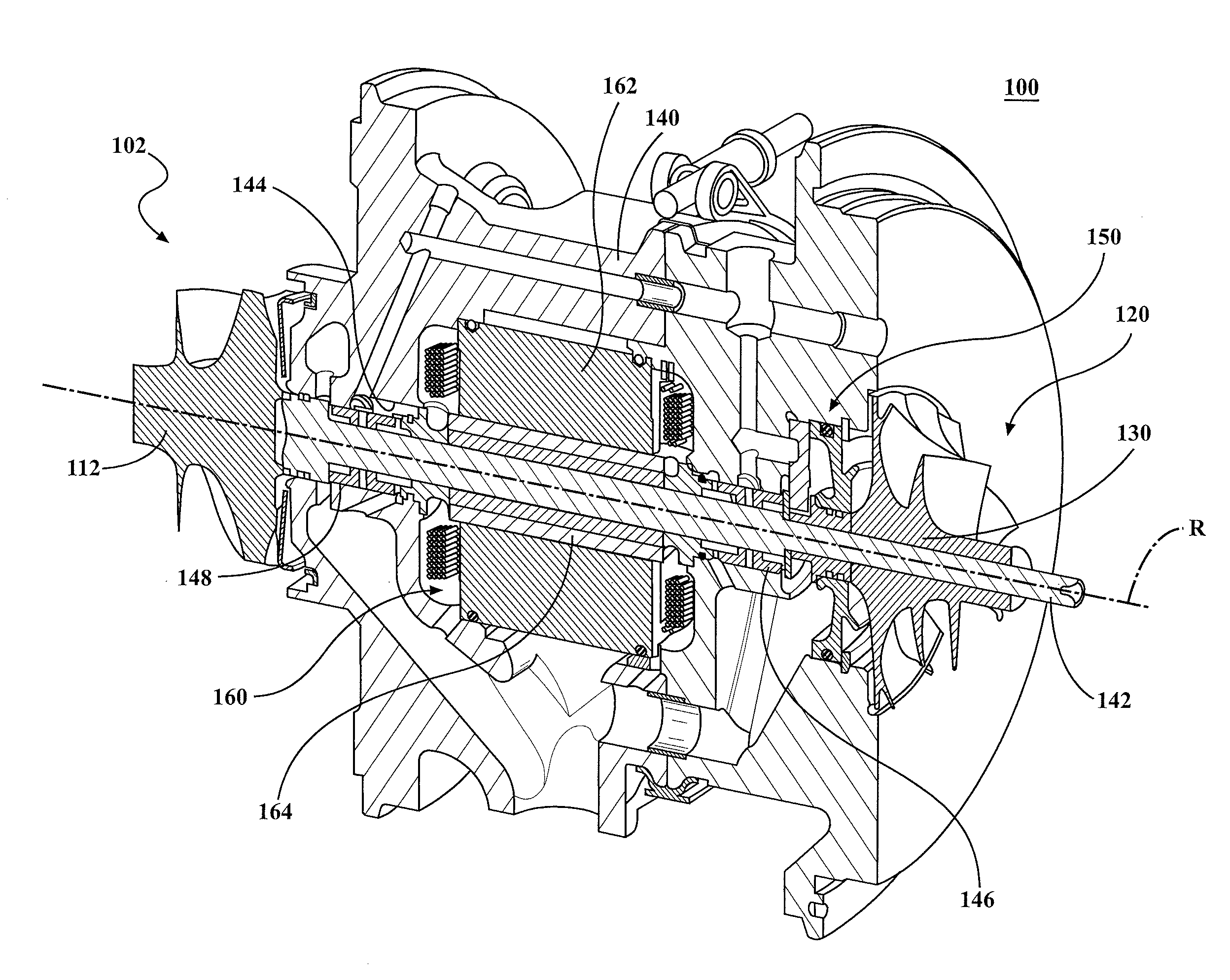
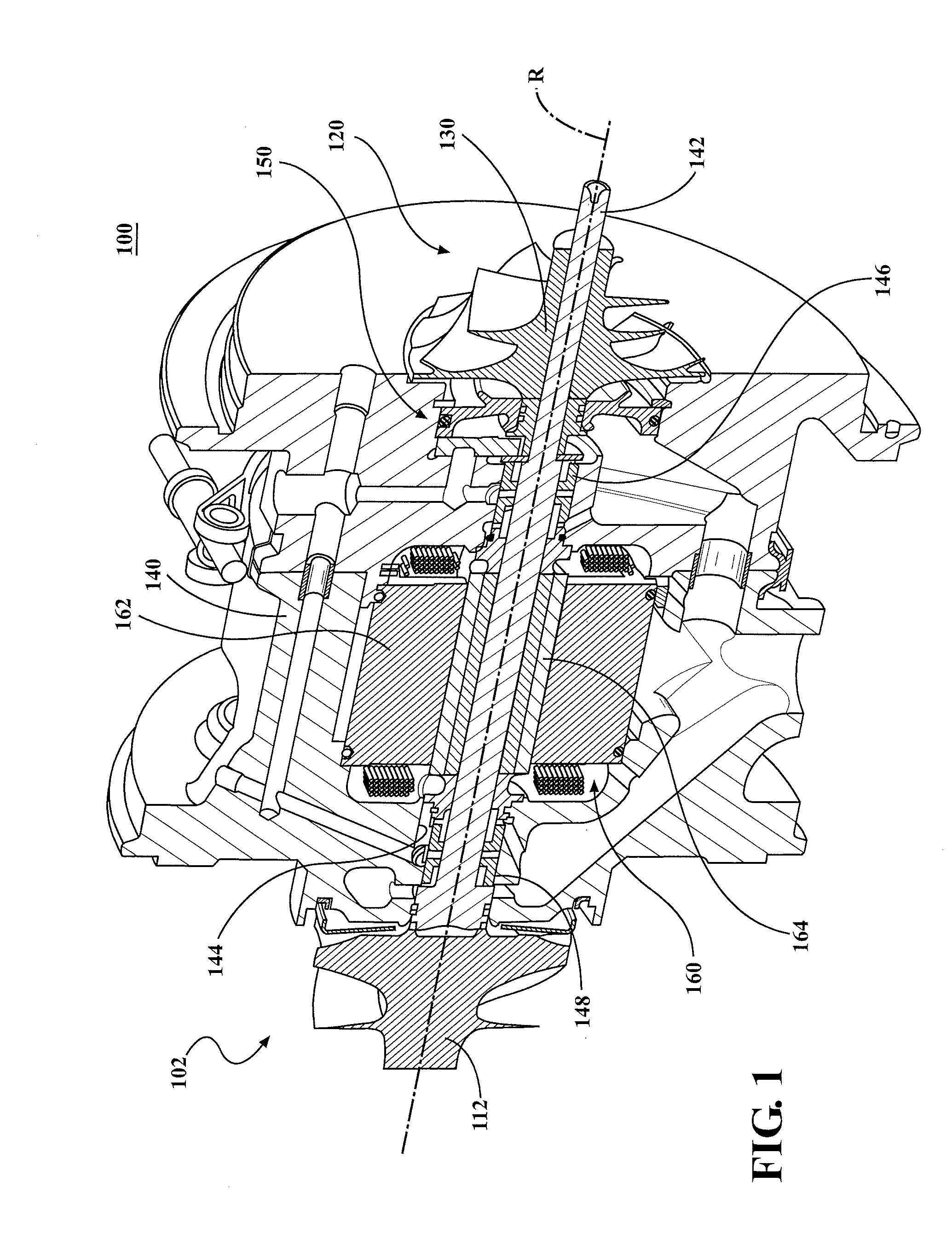
[0019]Referring to FIG. 1, an exhaust gas turbocharger 100 includes a turbine section 102, a compressor section 120, and a center bearing housing 140 disposed between and connecting the compressor section 120 to the turbine section 102. The turbine section 102 includes a turbine housing (not shown) that defines an exhaust gas inlet, an exhaust gas outlet, and a turbine volute disposed in the fluid path between the exhaust gas inlet and exhaust gas outlet. A turbine wheel 112 is disposed in the turbine housing between the turbine volute and the exhaust gas outlet.

[0020]The compressor section 120 includes a compressor housing (not shown) that defines an air inlet, an air outlet, and a compressor volute. A compressor wheel 130 is disposed in the compressor housing between the air inlet and the compressor volute.

[0021]A shaft 142 connects the turbine wheel 112 to the compressor wheel 130. The shaft 142 is supported for rotation about a rotational axis R within a bore 144 in the bearing ...


PUM


Abstract

A rotor assembly (164) is provided for a switched reluctance motor (160) in which nonmetallic, nonconductive pins (5) pass through a stack (2) of magnetic laminate plates (3).

Description

CROSS-REFERENCE TO RELATED APPLICATION[0001]This application claims priority to and all the benefits of U.S. Provisional Application No. 61 / 826,193 filed on May 22, 2013, and entitled “A High Speed Switch Reluctance Motor On A Turbocharger” which is incorporated herein by reference.BACKGROUND OF THE INVENTION[0002]1. Field of the Invention[0003]This invention relates to a hybrid turbocharger for an internal combustion engine. More particularly, this invention relates to a high speed switch reluctance motor for use in a hybrid turbocharger.[0004]2. Brief Description of the Related Art[0005]A turbocharger is a type of forced induction system used with internal combustion engines. Turbochargers deliver compressed air to an engine intake, allowing more fuel to be combusted, thus boosting an engine's power output without significantly increasing engine weight. Thus, turbochargers permit the use of smaller engines that develop the same amount of power as larger, normally aspirated engines...

Claims


Application Information

Patent Timeline
Patent Type & Authority Applications(United States)
IPC IPC(8): F04D25/06F04D17/10
CPCF04D17/10F04D25/06F02B39/10H02K1/246H02K1/30H02K19/103F02B37/10F02C6/12F01D15/10F05D2220/40Y02T10/12
Inventor CAVAGNARO, AUGUSTINECHEKANSKY, JASON W.RACE, ROBERT T.
Owner BORGWARNER INC
Why Eureka
Try Eureka