Mold molding method and mold molding member

a mold and molding technology, applied in the field of mold molding methods and mold molding members, can solve the problems of low general-purpose properties and unsuitable multi-product production, and achieve the effects of easy weight balance, hard mass balance, and easy weight balan

Active Publication Date: 2015-09-15
JAPAN STEEL WORKS M&E INC
View PDF12 Cites 0 Cited by
  • Summary
  • Abstract
  • Description
  • Claims
  • Application Information

AI Technical Summary

Benefits of technology

[0009]Also, the hollow ball proposed in PTL 1 is low in the connecting strength due to the spot-welded connection to raise a durability problem that the welded portion of the hollow ball may be broken in a mold dismantling operation such as a mold frame demolishing / collecting operation using a breaker. And, in the case of this hollow ball, since a space must be formed in the interior portion of the mold and the hollow ball must be used in this space, when the hollow ball is used simultaneously with the mold molding operation, sand may be flown into the hollow portion of the ball from the clearance thereof, so that the advantage that the ball is hollow may be lost. Also, the invasion of the sand into the hollow portion changes the bulk density of the mold, which may damage the balance of the mold and may worsen the collection efficiency of the molding sand.
[0025]According thereto, the mold is easy to balance in weight, and when loading the hollow sphere into the mold frame (molding frame), the floating and sinking of the hollow sphere due to the specific gravity difference are hard to occur. When the specific gravity (bulk specific gravity including the hollow portion) of the hollow sphere is less than 0.5 times the specific gravity of the molding sand, the hollow sphere is relatively extremely light and thus it is hard to balance in mass; and, when the hollow sphere is loaded among molding sand, it is easy to float up. On the other hand, when the specific gravity of the hollow sphere is more than 2.0 times the specific gravity of the molding sand, the hollow sphere becomes relatively heavy that the mass thereof is hard to balance, and the hollow sphere may be easy to sink when the hollow sphere is loaded among molding sand. That is, by reducing the specific gravity difference, influences on the overload and gravity in the mold handling operation can be reduced, and in a vibration molding method, the flow or separation of the hollow sphere such the sinking or floating thereof can be prevented. Further, this is effective in preventing from crushing and deforming of a pattern which is made of foaming polystyrene and has been put into use recently.

Problems solved by technology

However, these jigs are low in the general-purpose property and thus are not suitable for multi-product production.

Method used


Image

  • Mold molding method and mold molding member
  • Mold molding method and mold molding member
  • Mold molding method and mold molding member

Examples


example 1

[0037]In an example 1, there was used a metal frame having a product molding weight of 50 t and an internal capacity of a width 2,500 mm×length 4,500 mm×height 3,000 mm. Using mullite-system artificial sand and alkali phenol as the caking additive, a product was produced by self-hardening mold.

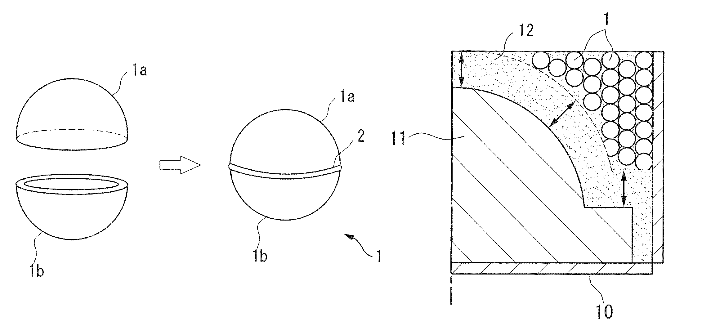
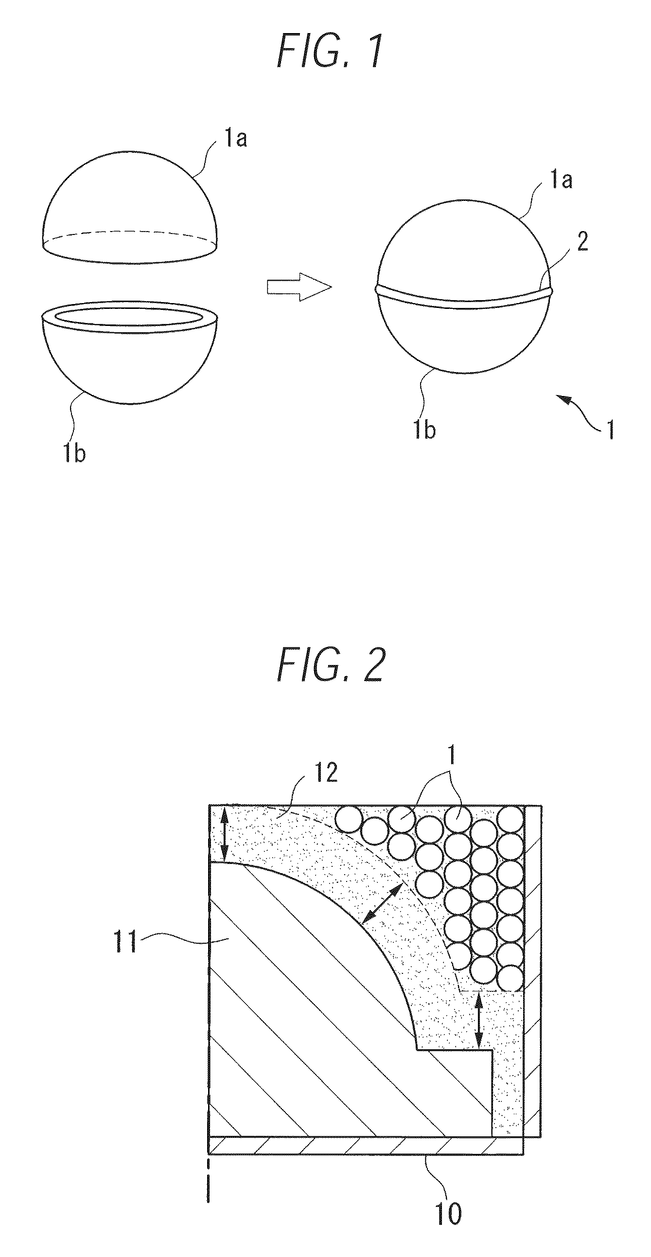
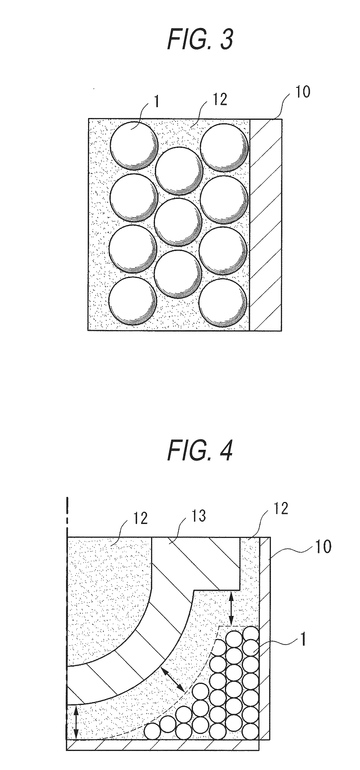
[0038]To produce a product having a shape shown in FIG. 4, the molding sand and iron balls 1 were disposed within the metal frame while they were spaced 300 mm or more from the pattern, thereby molding a mold. In this case, each iron ball had an outside diameter of 140 mm and had specific gravity substantially equal to the sand.

example 2

[0039]In an example 2, a product was produced by a self-hardening mold using zircon sand (specific gravity of 2.90) and the same alkali phenol. In this example, there were used iron balls each having a diameter of 120 mm and specific gravity of 2.5.

[0040]By using these iron balls, the quantity of sand necessary for filling was reduced 20% with respect to the related-art mass ratio.

[0041]Use of the iron balls having specific gravity that is substantially equal to the sand to be used can prevent the unstable balance or overload of the mold frame when handling the mold frame. Since the sand and iron balls were loaded spaced a given distance from the product, the molten metal did not leak during molding, and when demolishing the metal frame, heat influences on the iron balls such as melting loss and damage could not be found.

reference example 1

Mullite-System Artificial Sand

[0042]As a reference example 1, when producing a mold having the same condition as the example 1, there were used iron balls each having an outside diameter of 160 mm, weight of 7.5 kg and specific gravity of 3.5. Since a larger number of iron balls were loaded in the larger clearance portion, the center of gravity of the mold was biased, whereby, when reversing the mold, the mold and crane were damaged in some cases.

[0043]Further, since the mass of the mold was heavier, there was raised a fear that a lifting machine (crane or reversing machine) could be overloaded. In order to avoid this, the quantity of iron balls used had to be limited. Thus, the advantage of reducing the use quantity of sand was diminished when compared with the above-mentioned examples. Also, when an operator handles the mold (taking account of a situation where the operator works while having the iron balls in operator's hands), the mold provided a heavy load, so that the operatio...


PUM

PropertyMeasurementUnit
diameteraaaaaaaaaa
massaaaaaaaaaa
specific gravityaaaaaaaaaa

Abstract

An object is to provide a mold molding method which can provide a high general-purpose property and can reduce a usage quantity of molding sand. In a method for molding a mold (sand mold) by self-hardening molding sand using a caking additive, the mold is molded by disposing hollow spheres each formed to have no clearance therein among molding sand mixed with the caking additive. Preferably, the hollow sphere may be formed by working two metal plates to semispherical shapes and then connecting the semispherical-shaped metal plates to each other by welding their respective whole peripheries. A specific gravity of the hollow sphere may be 0.5 to 2.0 times a specific gravity of the molding sand.

Description

TECHNICAL FIELD[0001]The present invention relates to a mold molding method for molding a sand mold to produce castings, and a mold molding member for use in this mold molding method.BACKGROUND ART[0002]In a molding method for molding a mold using molding sand, a caking additive is mixed into the molding sand, the mixture is loaded into a mold metal frame and the molding sand is hardened to thereby mold a mold.[0003]Here, the mold metal frame is normally formed in a cuboid body, and a size thereof is determined according to the maximum width, height and length of a product. In this mold metal frame, since a wide clearance is produced due to a shape of a product that is not similar in shape to the mold metal frame, a large quantity of molding sand must be loaded into this clearance.[0004]In order to cope with this, there have been proposed a sand reducing method using a jig such as a jig of a type for mounting a partition having a shape similar to a product onto the inner surface of ...

Claims


Application Information

Patent Timeline
Patent Type & Authority Patents(United States)
IPC IPC(8): B22C9/02
CPCB22C9/02B22C9/24
Inventor TOMIGASHI, DAISUKEITABASHI, YOSHIKAZUKUBO, SEIJI
Owner JAPAN STEEL WORKS M&E INC
Why Eureka
Try Eureka