Electrical plug connector assembly

a technology of electrical plug connectors and assembly parts, applied in the direction of coupling contact members, fixed connections, coupling device connections, etc., can solve the problems of reducing the production wasting time, and achieve the effect of reducing the soldering process and increasing the fabrication rate of electrical plug connectors

Active Publication Date: 2016-06-02
ADVANCED CONNECTEK INC
View PDF1 Cites 14 Cited by
  • Summary
  • Abstract
  • Description
  • Claims
  • Application Information

AI Technical Summary

Benefits of technology

[0008]The main objective of the invention is to provide an electrical plug connector assembly that solders two sets of soldering sections of terminals on a single surface of a circuit board to decrease the soldering processes, which increases the fabrication rate of the electrical plug connector.

Problems solved by technology

Therefore, the soldering processes waste time and lower the production rate of the electrical connector.

Method used


Image

  • Electrical plug connector assembly
  • Electrical plug connector assembly
  • Electrical plug connector assembly

Examples


first embodiment

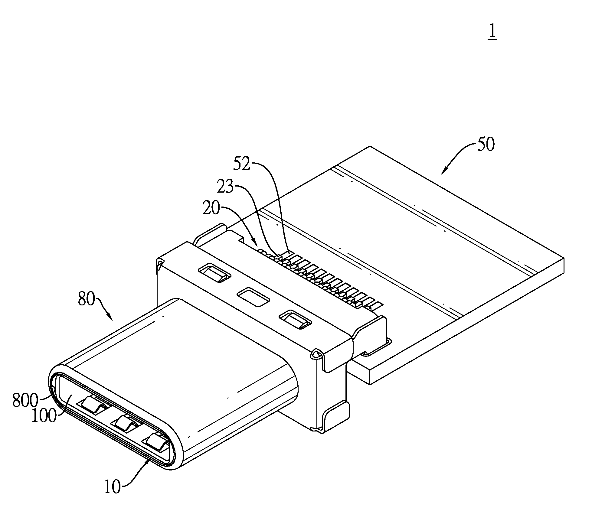
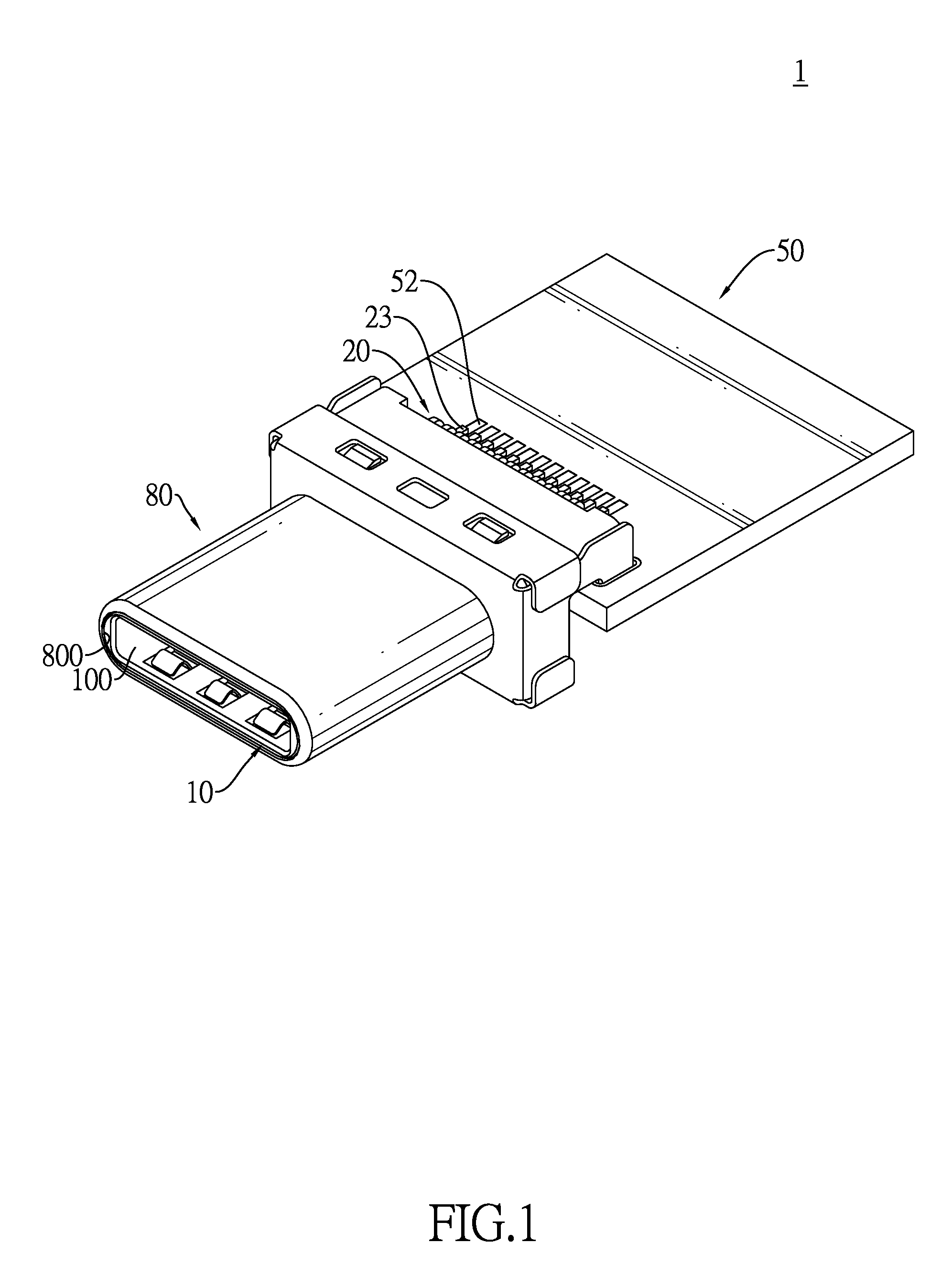
[0023]With reference to FIGS. 1 and 2, an electrical plug connector assembly in accordance with the present invention may be a USB Type-C connector, and complies with the USB Type-C Cable and Connector Specification ver. 0.98C set by the USB implementers Forum (USB IF).

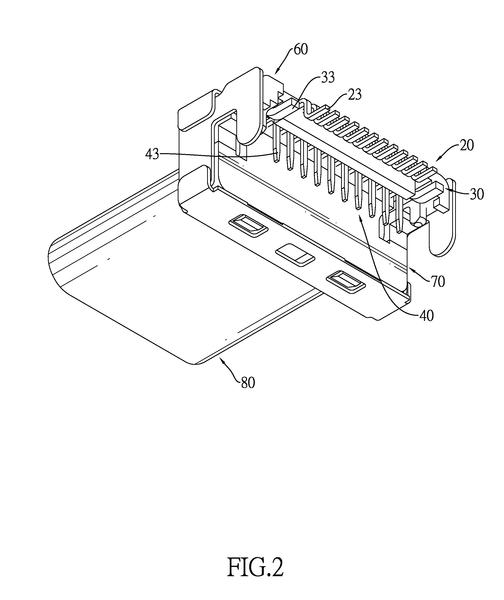
[0024]With further reference to FIGS. 3 and 4, the electrical plug connector assembly comprises an insulative housing 10, a first terminal set, a second terminal set, two resilient hooking arms 30, a grounding plate 35, a circuit board 50, an upper rear plug bracket 60, a lower rear plug bracket 70 and a shell 80.

[0025]The insulative housing 10 is substantially horizontally symmetrical and has a top board 101, a bottom board 102, two opposite sidewalls 103, an insertion space 100, an assembling slot 17, two positioning slots 11, an upper pressing element 15 and a lower pressing element 16.

[0026]The top board 101 has multiple upper through holes 105. The upper through holes 105 are defined through the top board 101 and...

second embodiment

[0055]With further reference to FIGS. 6 and 7, in the electric plug connector in accordance with the present invention, the first soldering sections 23a of the first conductive terminals 20 are SMT type soldering legs, and the second soldering sections 43a of the second conductive terminals 40 are DIP type soldering legs. The first soldering portions 52a of the circuit board 50a are SMT type soldering pads. The second soldering portions 54a are DIP type through holes that are staggeredly arranged.

third embodiment

[0056]With further reference to FIGS. 8 and 9, in the electric plug connector in accordance with the present invention, the first soldering sections 23b of the first conductive terminals 20 are SMT type soldering legs, and the second soldering sections 43b of the second conductive terminals 40 are SMT type soldering legs. The first soldering portions 52b of the circuit board 50b are SMT type soldering pads. The second soldering portions 54b are SMT type soldering pads.


PUM


Abstract

An electrical plug connector assembly has an insulative housing, a first terminal set, a second terminal set and a circuit board. The first and second terminal sets are mounted in the insulative housing. The first terminal set has multiple first conductive terminals each including a first soldering section. The second terminal set has multiple second conductive terminals each including a second soldering section. The first and second soldering sections are soldered on an identical surface of the circuit board such that only one single soldering process is required to solder all of the first and second conductive terminals to the circuit board. The production rate of the electrical plug connector assembly is therefore improved.

Description

BACKGROUND OF THE INVENTION[0001]1. Field of the Invention[0002]The present invention relates to an electrical connector, and more particularly to an electrical plug connector assembly that solders two sets of soldering sections of terminals on a single surface of a circuit board to decrease the soldering processes, which increases the fabrication rate of the electrical plug connector.[0003]2. Description of Related Art[0004]Electrical connectors are common electrical components mounted on electronic devices and may be connected to corresponding electrical connectors on other electronic devices for signal transmission or power supply between the connected electronic devices.[0005]A conventional electrical connector such as a universal serial bus (USB) 3.0 Type-C electrical plug connector has an insulative housing, two sets of terminals, a circuit board and a metal shell. The sets of the terminals are mounted on the insulative housing for signal transmission and each terminal of each...

Claims


Application Information

Patent Timeline
Patent Type & Authority Applications(United States)
IPC IPC(8): H01R12/57H05K1/11
CPCH05K1/111H01R12/57H01R13/02H01R12/724H01R12/725H01R24/60H05K1/115H05K1/117H05K2201/094H05K2201/09409H05K2201/10295H05K2201/1034
Inventor KAO, YA-FENTSAI, YU-LUNHOU, PIN-YUANLIAO, CHUNG-FUZHOU, YANG-YANG
Owner ADVANCED CONNECTEK INC
Why Eureka
Try Eureka