

Electric brake system
- Summary
- Abstract
- Description
- Claims
- Application Information
AI Technical Summary
Benefits of technology
Problems solved by technology
Method used
Image

Examples
Embodiment Construction
[0031]Reference will now be made in detail to the embodiments of the present invention, examples of which are illustrated in the accompanying drawings, wherein like reference numerals refer to like elements throughout.
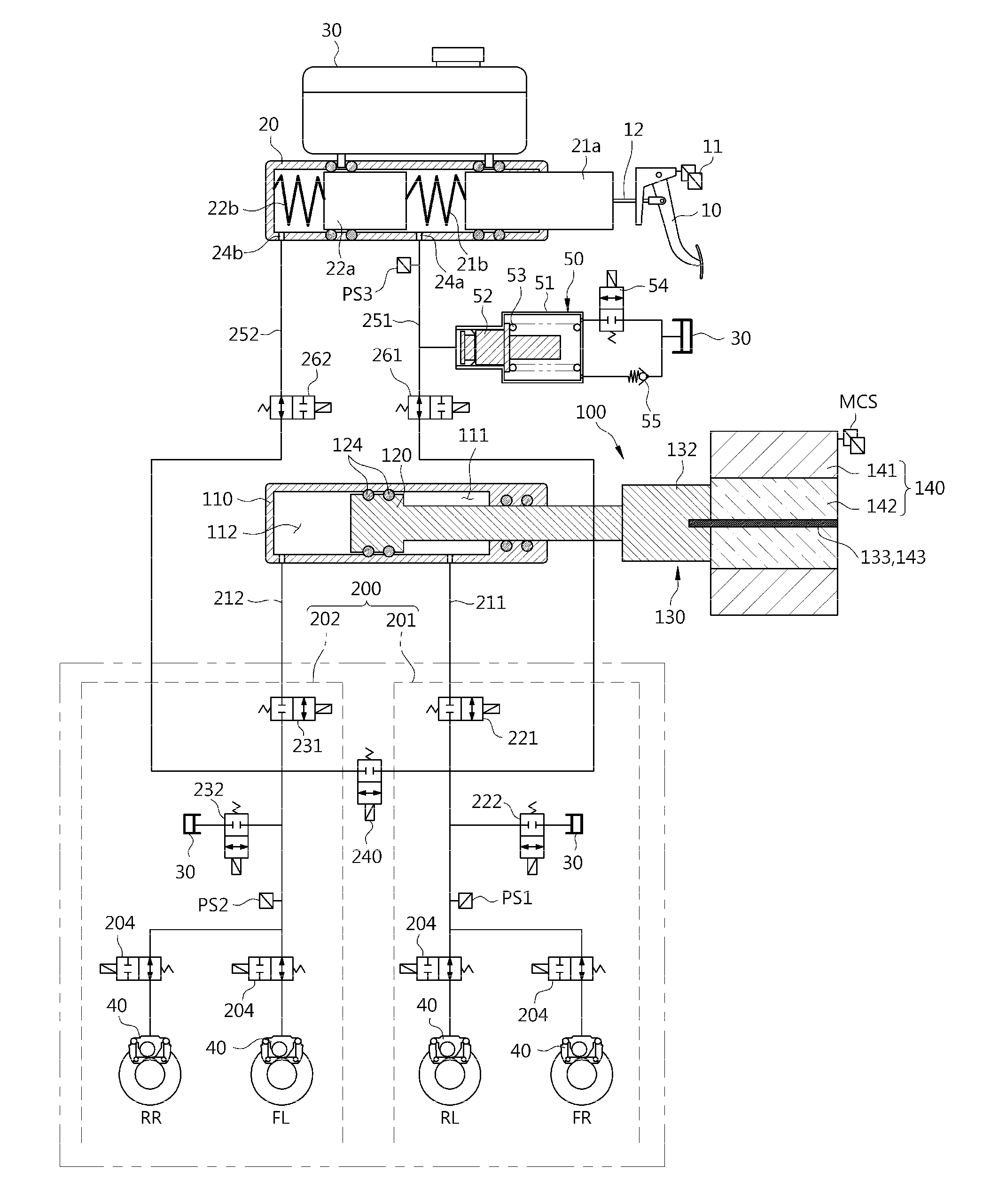
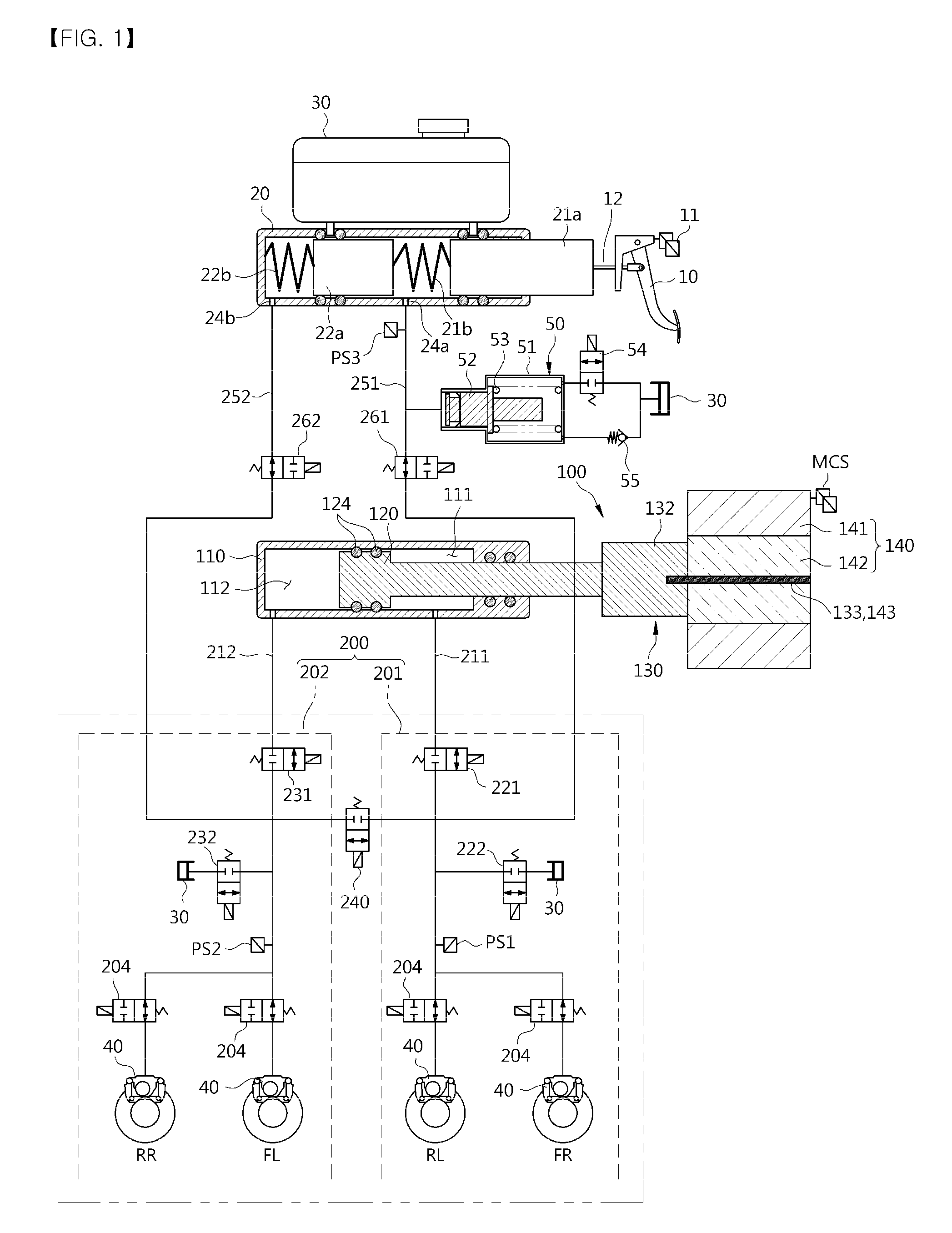
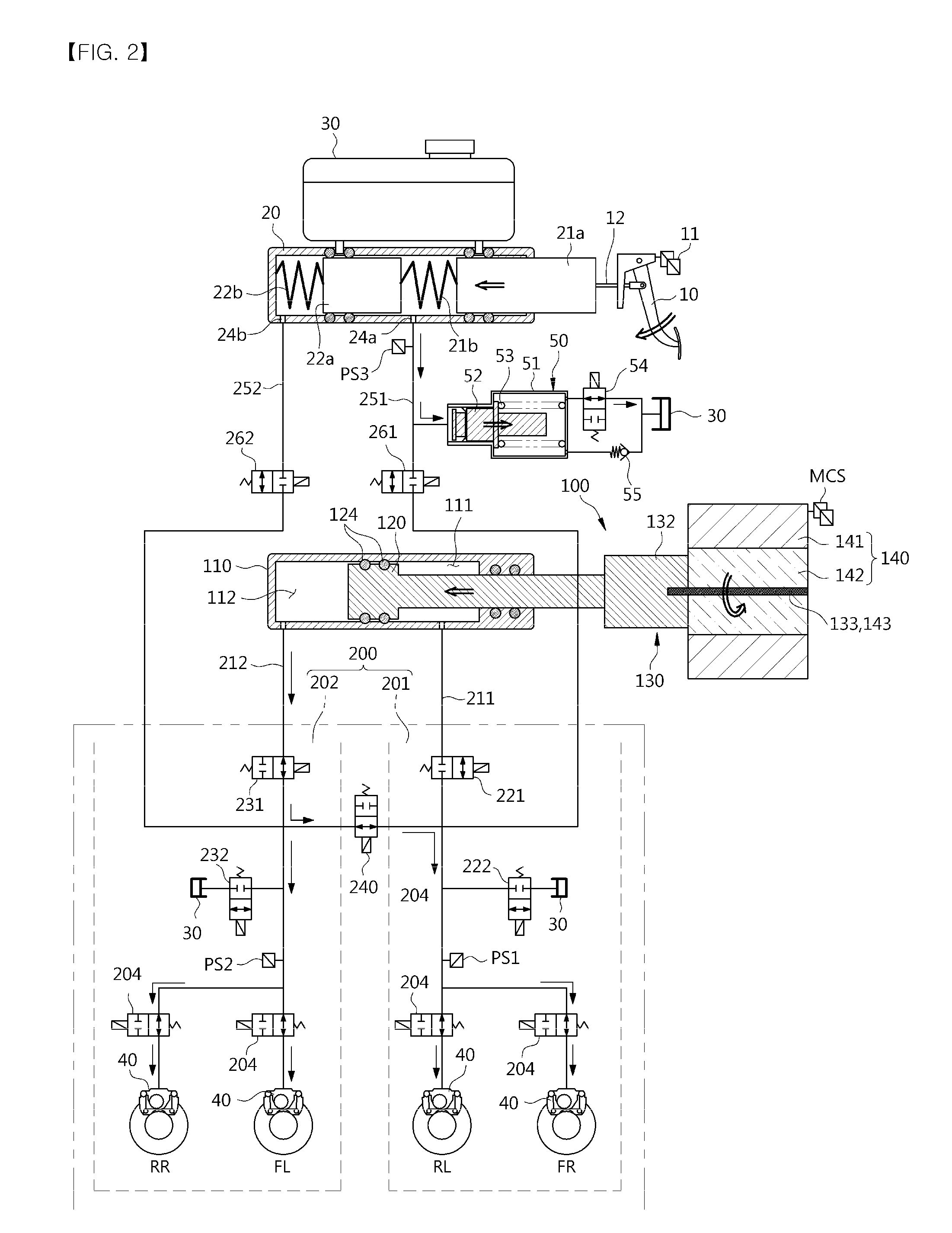
[0032]FIG. 1 is a hydraulic circuit view illustrating a non-brake state of an electric brake system according to an embodiment of the present invention.
[0033]Referring to FIG. 1, an electric brake system generally includes, a master cylinder 20 to generate hydraulic pressure, a reservoir 30 coupled to the upper portion of the master cylinder 20 to store oil, an input rod 12 to apply pressure to the master cylinder 20 according to foot force applied to a brake pedal 10, a caliper brake 40 to perform braking of the respective wheels (RR, RL, FR, FL) when the oil in the reservoir 20 is transferred thereto, and a pedal displacement sensor 11 to sense displacement of the brake pedal 10.
[0034]Herein, the master cylinder 20 may be provided with at least one chamber to generat...
PUM
 Abstract
Description
Claims
Application Information