Exhaust soot control system

a control system and exhaust soot technology, applied in the direction of engines, mechanical equipment, machines/engines, etc., can solve the problems of difficult to reach the regeneration temperature of the sensor, inaccurate voltage and current readings across the gap, exhaust to the atmosphere, etc., and achieve the effect of reducing soot emissions

Active Publication Date: 2016-06-09
FORD GLOBAL TECH LLC
View PDF2 Cites 8 Cited by
  • Summary
  • Abstract
  • Description
  • Claims
  • Application Information

AI Technical Summary

Benefits of technology

[0001]Engine combustion may generate soot, which can be exhausted to the atmosphere. To reduce soot emissions, a particulate filter may be used. To sense the soot produced and / or released, a soot sensor may be used.

Problems solved by technology

Engine combustion may generate soot, which can be exhausted to the atmosphere.
For example, non-uniform soot deposit on the surface can occur due to bias flow distribution across the sensor surface, resulting in inaccurate voltage and current readings across the gap.
Additionally, or alternatively, it can be difficult to reach sensor regeneration temperature due to large flow impingement on the surface in some sensor designs.
Further still, contamination may be problematic due to large particulate or water droplet impingement on the sensor surface.

Method used


Image

  • Exhaust soot control system
  • Exhaust soot control system
  • Exhaust soot control system

Examples


Embodiment Construction

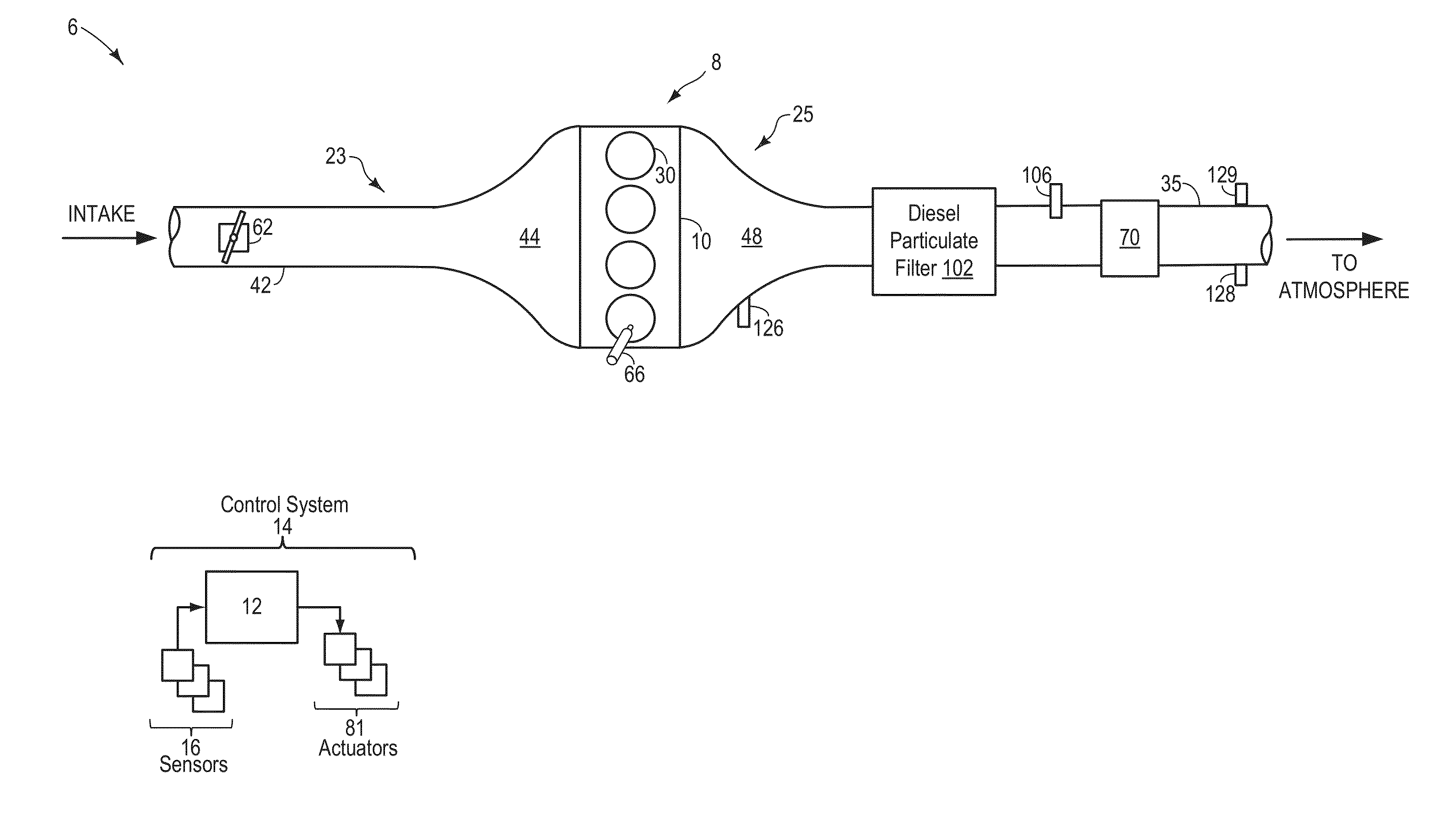
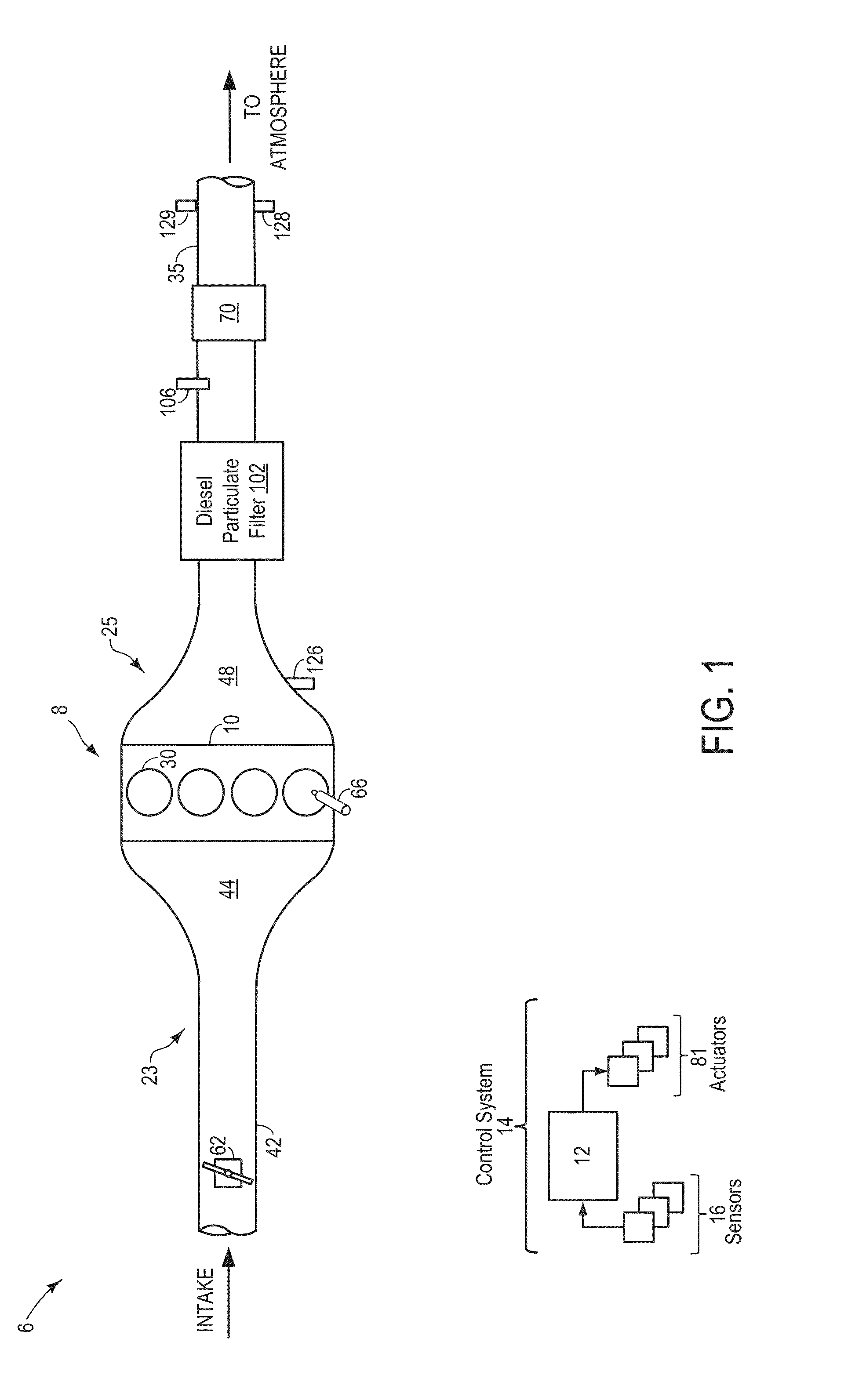
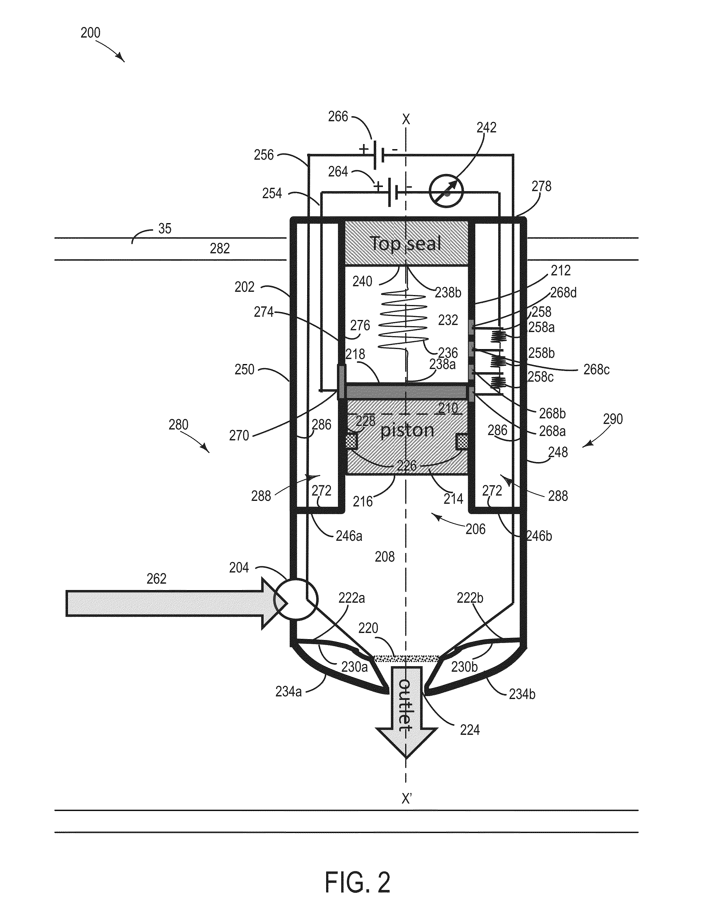
[0011]The following description relates to systems and methods for controlling a particulate matter (PM) retaining system, such as the diesel particulate filter of FIG. 1. As shown therein, the PM retaining system may include a diesel particulate filter (DPF) and a pressure-based soot sensor positioned downstream of the filter. As shown in FIG. 2, the pressure-based soot sensor intakes a portion of the exhaust gas, where the soot (particulate matter) accumulates onto its filter as the exhaust gas exits the sensor assembly through the outlet. Specifically, the exhaust gas flows from the outlet of the particulate filter to the upstream-facing inlet of the soot sensor assembly. The pressure based soot sensor assembly may be constructed in such a way as the exhaust outlet faces radially into a centerline of the exhaust passage. The accumulation of the soot in the soot sensor filter decreases the filter flow permeability, increasing the pressure inside the sensor chamber. With an increas...


PUM


Abstract

Systems and methods are described for sensing soot (particulate matter) in an exhaust system of a vehicle. An example system comprises a sensor housing an exhaust inlet, an exhaust outlet, and a soot filter affixed across the exhaust outlet, and a piston with the housing, affixed to a spring via a conductive surface, the spring fluidly separated from the exhaust chamber by a piston seal. The system may further comprise a detection circuit including the conductive surface of a piston and a plurality of resistive elements and a separate regeneration circuit configured to supply electric heat across the soot filter to regenerate the sensor.

Description

BACKGROUND AND SUMMARY[0001]Engine combustion may generate soot, which can be exhausted to the atmosphere. To reduce soot emissions, a particulate filter may be used. To sense the soot produced and / or released, a soot sensor may be used.[0002]Soot sensors may include various types. For example, as described by U.S. Pat. No. 8,310,249, soot sensors collect particles on charged electrodes. In one example, a soot sensing arrangement for includes a pair of spaced apart electrodes having an insulator interposed therebetween, where the first electrode, second electrode and insulator extend into the exhaust flow. As the exhaust flow impinges on the first electrode, second electrode and insulator, any soot or particulate therein can likewise impinge thereon. A voltage supply operably coupled to the first and second electrodes provides a predetermined voltage between the first and second electrodes and a current sensor operably coupled to the first and second electrodes senses current betwee...

Claims


Application Information

Patent Timeline
Patent Type & Authority Applications(United States)
IPC IPC(8): F01N3/033
CPCF01N3/033F01N9/002F01N3/027F01N2560/05F01N2560/20F01N2900/1606F02D2200/0812Y02T10/40
Inventor ZHANG, XIAOGANG
Owner FORD GLOBAL TECH LLC
Why Eureka
Try Eureka