Ventilation module with swirler fan

a technology of swirler fan and ventilation module, which is applied in the direction of ventilation system, heating type, piston pump, etc., can solve the problems of contaminant cannot be carried out with air, light air is exhausted, suction power rapidly drops, etc., to achieve efficient exhaustion, eliminate pollutants and odors, and strong suction and discharge power

Active Publication Date: 2016-06-09
TORNADO SYST
View PDF17 Cites 13 Cited by
  • Summary
  • Abstract
  • Description
  • Claims
  • Application Information

AI Technical Summary

Benefits of technology

[0046]According to the disclosure, it is possible to provide a exhaust fan or a range hood or a portable dust collector that exhibits strong suction and discharge power by forming an extremely strong tornado air current due to a dual stage fans of a ventilator module that suctions air at high velocity in the ventilation apparatuses. That is, a swirl generated by a swirler fan forms a donut-like low pressure zone so that the air at the lower part, which forms a relatively high pressure zone, ascends at a high velocity, and the air adjacent to the swirler fan is strongly suctioned and discharged by the drive of the suction fan.
[0047]In this aerodynamic mechanism, some portion of inducing air via the opening at the center of the swirler fan can be re-diffused to the direction of circumference due to the air forces pushing outward by the rotation of fins on the annular disk. An annular band with a certain height erected vertically in between the inner side of the planer ring-shape main body and the connection rods to the center does a role of preventing inducing air via the opening at the center of the swirler fan from re-diffusing to the direction of circumference, and exhausting efficiently to the outlet.
[0048]According to the ventilator module of the disclosure, compared to a ventilation fan by a sirocco fan of the related art, it is possible to exhibit the suction and discharge power over the greater wide range of area, and to eliminate pollutants and odors speedily due to the high velocity of the ascending air current.
[0049]In addition, a bell-mouth according to the disclosure may induce the formation of the donut-like low pressure zone over the more extended range at the periphery of the swirler fan so as to enlarge and maintain the center portion of the tornado air current thereby widening the generation area of the ascending air current.
[0050]According to the ventilator module of the disclosure employing the dual structure of fans and the bell-mouth, it is possible to powerfully and speedily discharge pollutants and odors in the space with a relatively low power and little noise because it doesn't need to increase wasteful airflow rate to increase air velocity as the conventional fans of the related art do.

Problems solved by technology

It means that in case the air velocity generated by a ventilation fan is lower than the minimum capture velocity, the contaminants can't be carried out with the air but just light air are exhausted.
Such a ventilation fan of the related art is disadvantageous in that the capture region of contaminants is only defined at the part adjacent to an inlet as illustrated in the diagram of simulation of FIG. 1.
Due to such a property, the suction power rapidly drops unless the exhaust fan is installed to be adjacent to a source to generate contaminants.
However, according to Fan Affinity Law, in order to double the air velocity, it is necessary to increase the power consumption of a fan by 23, that is, eight times (cubic law of air velocity), which is problematic because the power consumption becomes too great and accordingly, the noise thus caused increases.

Method used


Image

  • Ventilation module with swirler fan
  • Ventilation module with swirler fan
  • Ventilation module with swirler fan

Examples


Embodiment Construction

[0062]Hereinafter, preferred embodiments of the disclosure will be described in detail, with reference to the attached drawings.

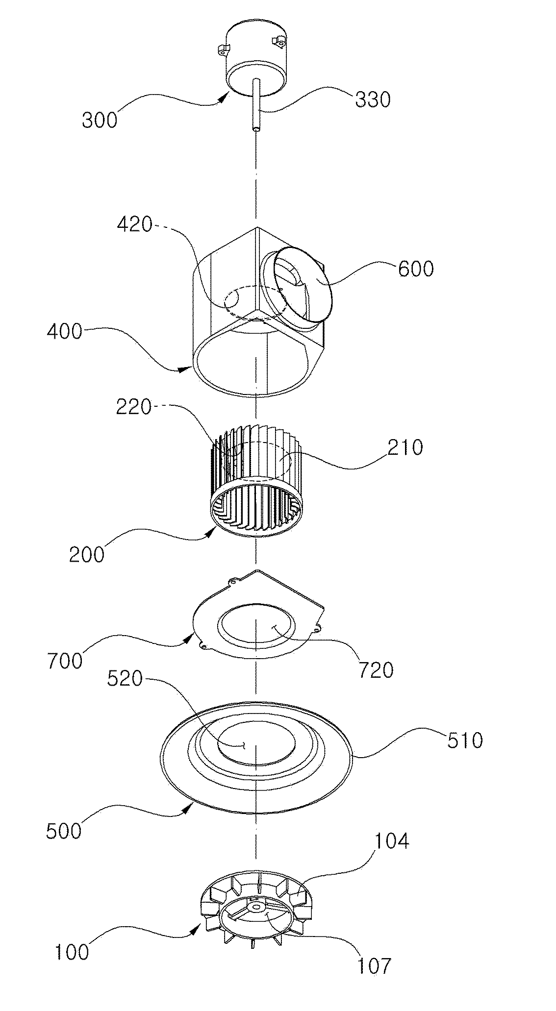
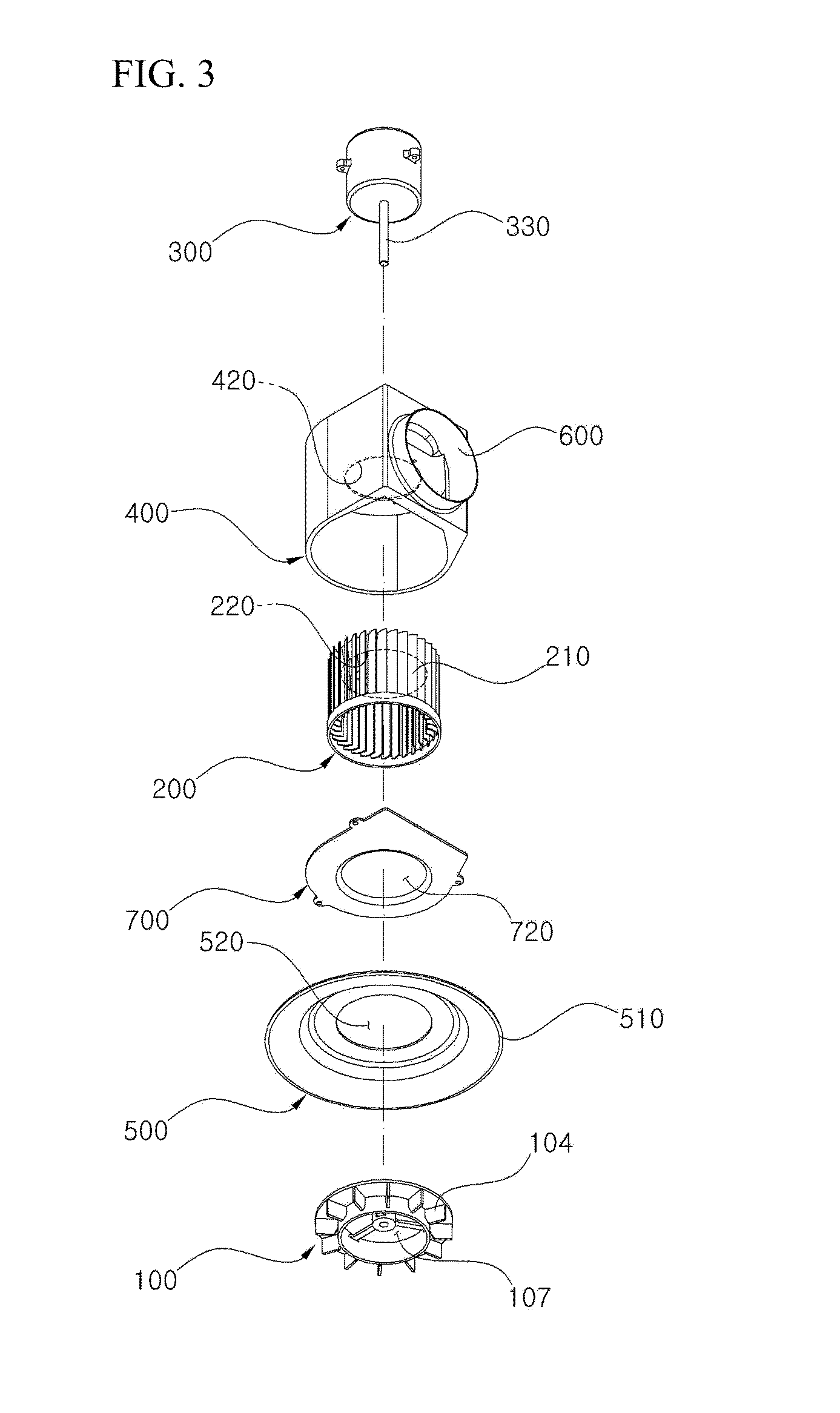
[0063]FIG. 3 is an exploded perspective view that illustrates a configuration of a ventilator module according to the disclosure.

[0064]A ventilator module according to the present exemplary embodiment includes a swirler fan 100, a suction fan 200, and a motor 300. The ventilator module may further include a suction fan case 400, a bell-mouth 500, an outlet 600 and a housing 700.

[0065]A swirler fan 100 provided with an opening 107 at the center thereof, and an suction fan 200 arranged at the rear side of the swirler fan 100 are coupled with one motor 300 via coupling members so as to be simultaneously driven. The two fans are assembled to be coupled with the motor 300 being maintained on the same axis which is an axis 330 of the motor.

[0066]FIG. 4 is a cut exploded perspective view of the range hood configured with the ventilator module according to the disc...


PUM


Abstract

The disclosure aims to provide a ventilator module with improved efficiency. The ventilator module employs the dual structure of fans includes a swirler fan and a suction fan, in which the swirler fan is disposed at the front side and the suction fan is disposed at the rear side of the swirler fan so that a swirl formed by the drive of the swirler fan forms a donut-like low pressure zone around an inlet, and a tornado is formed by rotating the donut-like low pressure zone by the drive of the suction fan thereby cause the air below swirler fan to ascend at high velocity so as to be suctioned and discharged.

Description

[0001]The present application claims priority from Korean Patent Application No. 2014-0175073, filed on Dec. 8, 2014, which is hereby incorporated by reference for all purposes as if fully set forth herein.BACKGROUND[0002]1. Field[0003]The disclosure relates to a ventilation system, more particularly to a ventilation apparatus employing a swirler fan formed with plural fins on an annular disk with the opening at the center portion to improve efficiency.[0004]2. Description of Related Art[0005]Air moves from high atmospheric pressure region to low atmospheric pressure region. The mechanical fans are utilizing this aerodynamic principle. Rotating blades pushes air outwards and thereby the atmospheric pressures around the blades are lowered. Then air in surroundings in relatively high atmospheric pressure moves toward the blades. By the directions of blades' distortion, air is suctioned or discharged.[0006]A ventilation fan is used to eliminate contaminants (gases, dusts or particles) ...

Claims


Application Information

Patent Timeline
Patent Type & Authority Applications(United States)
IPC IPC(8): F24F7/06F04D25/08F04D25/16
CPCF24F7/065F04D25/08F04D25/163F04D25/166F04D19/002F04D29/281F04D29/282F24F13/06F24F2221/14F04D29/44F24F7/10F24F13/08F24F2013/205F04D17/16F04D17/164F04D29/283
Inventor OH, HEE BUM
Owner TORNADO SYST
Why Eureka
Try Eureka