Mechanical High-G Shock Testing Machines

Active Publication Date: 2016-06-09
OMNITEK PARTNERS LLC
View PDF8 Cites 14 Cited by
  • Summary
  • Abstract
  • Description
  • Claims
  • Application Information

AI Technical Summary

Benefits of technology

The patent text describes the need for better mechanical shock testing machines that can quickly and easily test a lot of components. These machines should allow for easy mounting of components and access to them, unlike other methods that use piston platforms or limit access. The technical effect of this invention is the ability to efficiently and accurately test a large number of components in a short period of time.

Problems solved by technology

The developed methods should not be based on the use of the actual or similar platforms, for example, firing projectiles carrying the test components with similar guns such as the described in the method “9” above, due to the cost and difficulty in providing full instrumentation which would allow testing of a few components at a time, thereby making the cost of engineering development of such components and their reliability testing which requires testing of a large number of samples prohibitively high.

Method used


Image

  • Mechanical High-G Shock Testing Machines
  • Mechanical High-G Shock Testing Machines
  • Mechanical High-G Shock Testing Machines

Examples


embodiment 30

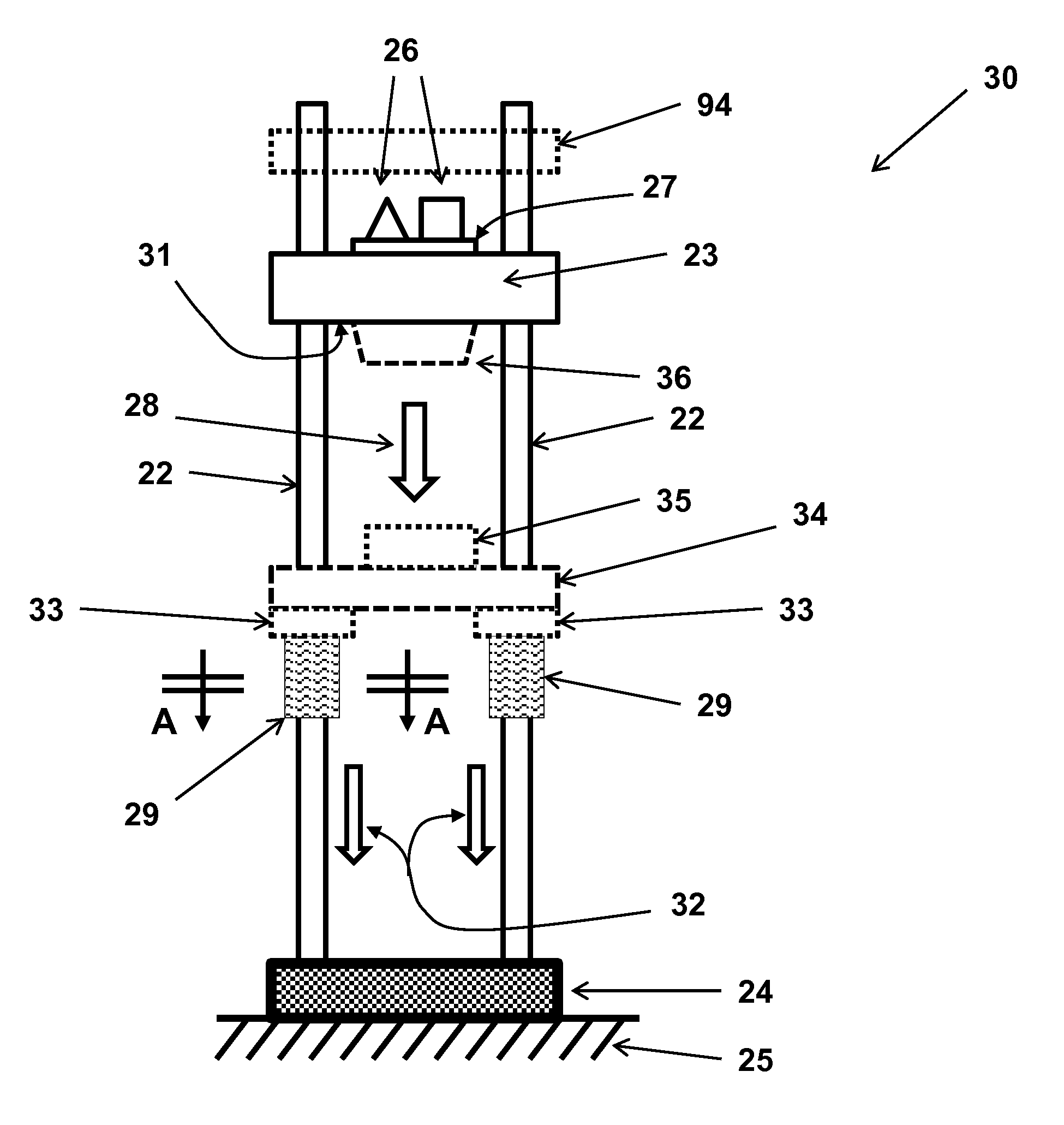
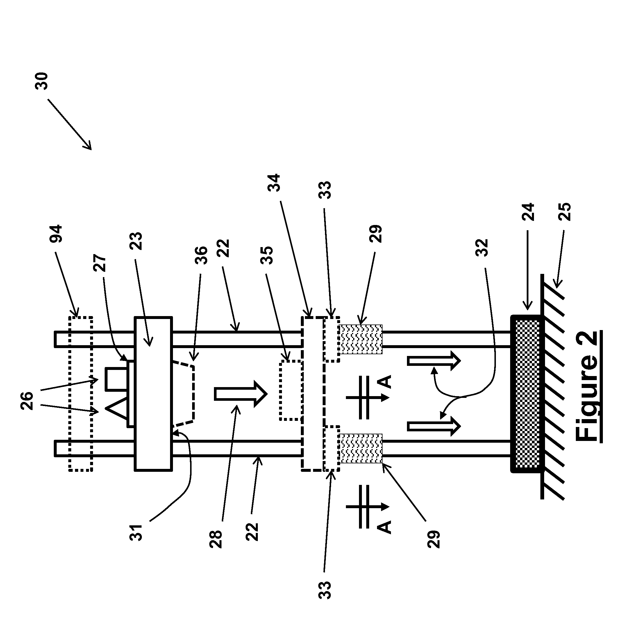
[0084]A schematic of a first mechanical shock testing machine embodiment 30 is shown in FIG. 2. The basic structure of the mechanical shock testing machine 30 is the same as the shock testing machine 10 of the prior art shown in the schematic of FIG. 1. The schematic of FIG. 2 is intended to show only the main components of the present mechanical shock testing machine 30. The mechanical shock machine 30 is similarly constructed with some type of rails 22 along which the impact mass element 23 travels. The rails (one or more) may have any cross-sectional shape and the sliding surfaces between the mass element 23 and the rails 22 may be covered with low friction material or may utilize rolling elements to minimize sliding friction. The rails 22 are generally mounted on a relatively solid and massive base 24, which in turns rests on a firm foundation 25. Certain relatively stiff shock absorbing elements (not shown) may be provided between the base 24 and the ground 25 to prevent damage...

embodiment 50

[0102]In the mechanical shock testing embodiment 50, the braking elements 51 are initially applying no braking force to the rails 22, i.e., the brake pads (similar to the pads 37 shown in FIG. 4) are not pressed against the surface of the rails 22. This would therefore allow the assembly of the mass element 52 and braking elements 51 to be accelerated downwards (under gravity for vertically installed shock testing machines and / or pre-tensioned bungee cords or pneumatic cylinders or other similar means as was previously described) to gain a predetermined velocity. Then once the mass element and braking element assembly has gained the predetermined velocity, the braking elements 51 are engaged and begin to apply a prescribed level of braking force to the rails 22, thereby causing the mass element 52 to be decelerated at the desired rate, thereby subjecting the testing components 53 to a predetermined and essentially constant deceleration (shock) pulse that lasts until the assembly of ...

embodiment 29

[0107]As can be seen in the schematic of FIG. 6, the relatively thin (flexible) strap 55 (element 39 in the embodiment 29 of FIG. 4) which is made out of high strength material (such as spring steel) is provided with extended ends 56. A spacing element 57 is positioned between the extended ends 56. A pair of bolt 58 and nut 59 is passed through provided holes (not shown) in the extended ends 56, and is used to preload the compressive spring 60. The spacing element 57 can be provided with a slight wedging angle to make it easier to be pulled out from between the extended ends 56 in the direction of the arrow 62 by the cable 61. Once the spacing element 57 has been pulled out, the preloaded compressive spring 60 would apply a force to the extended ends 56 that tends to bring them together, thereby applying a compressive force to the brake pads 37, thereby generating the desired braking force between the braking elements 51 and the rails 22 to begin to decelerate the mass element 52 an...


PUM


Abstract

A shock testing machine including: a movable impact mass upon which one or more components to test are mounted; one or more rails upon which the impact mass is movable; and a brake operatively engageable with the movable impact mass after the movable impact mass has moved a predetermined distance to retard the movement of the movable impact mass such that the components to be tested experience a deceleration profile.

Description

CROSS-REFERENCE TO RELATED APPLICATIONS[0001]This application claims the benefit of priority to U.S. Provisional Application Ser. No. 61 / 884,915, filed on Sep. 30, 2013, the entire contents of which is incorporated herein by reference.BACKGROUND OF THE INVENTION[0002]1. Field of the Invention[0003]The present invention relates generally to a shock and impact testing machine for subjecting the components to be tested to an acceleration pulse of a prescribed amplitude and duration, and more particularly for testing various devices and components of gun-fired or mortar or electrically powered rail gun or the like munitions as well said munitions by subjecting them to similar launch acceleration pulses.[0004]2. Prior Art[0005]Gun-fired munitions, mortars and rail-gun munitions are subjected to high-G (setback and set-forward) acceleration during the launch. Almost all munitions are also subjected to shock loading upon target impact. High-G shock loading is also experienced by rockets du...

Claims


Application Information

Patent Timeline
IPC IPC(8): G01M7/08G01N3/307
CPCG01N3/307G01M7/08G01N3/303
Inventor RASTEGAR, JAHANGIR S.FISCHER, JACQUES
Owner OMNITEK PARTNERS LLC
Why Eureka
Try Eureka