Method and System for Eliminating Low Frequency Oscillation Between Generators

a generator and low frequency technology, applied in the direction of electric generator control, dynamo-electric converter control, emergency protective circuit arrangement, etc., can solve the problem of dramatic power fluctuation on transmission lines, inability to effectively damp the inter-area oscillation, and the effect of reducing the power fluctuation of transmission lines

Active Publication Date: 2016-06-09
WEI QIANG +1
View PDF8 Cites 11 Cited by
  • Summary
  • Abstract
  • Description
  • Claims
  • Application Information

AI Technical Summary

Benefits of technology

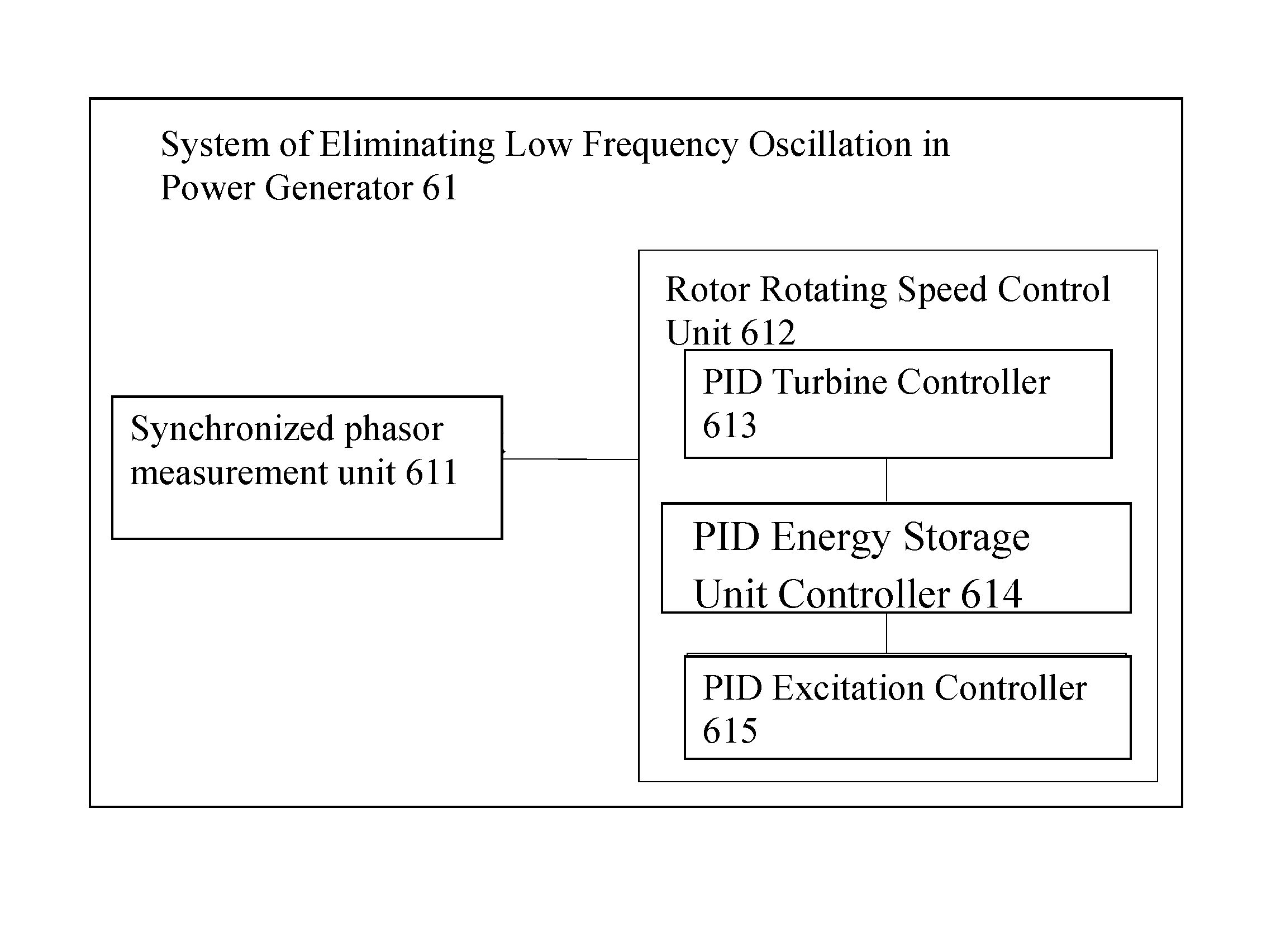
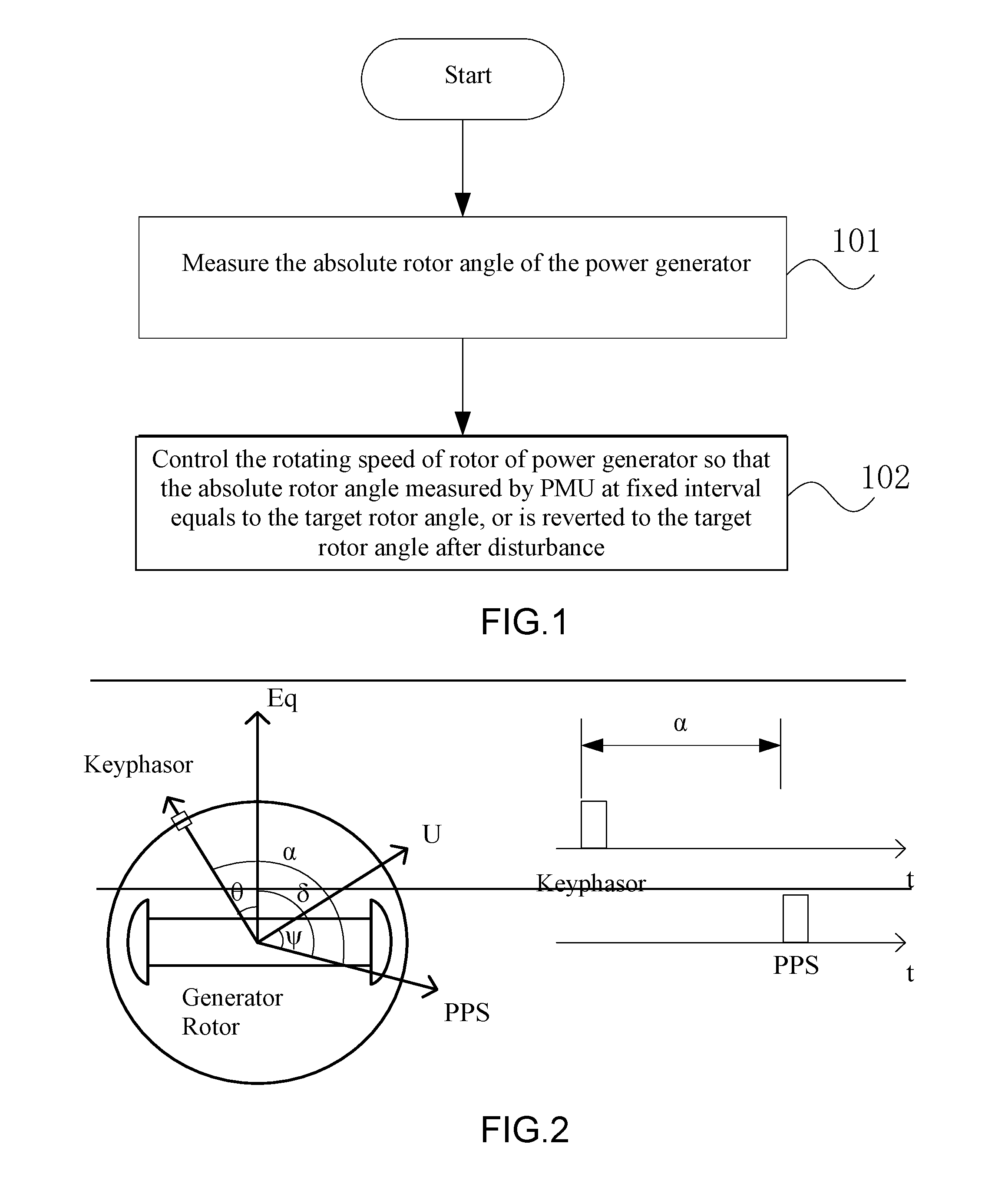
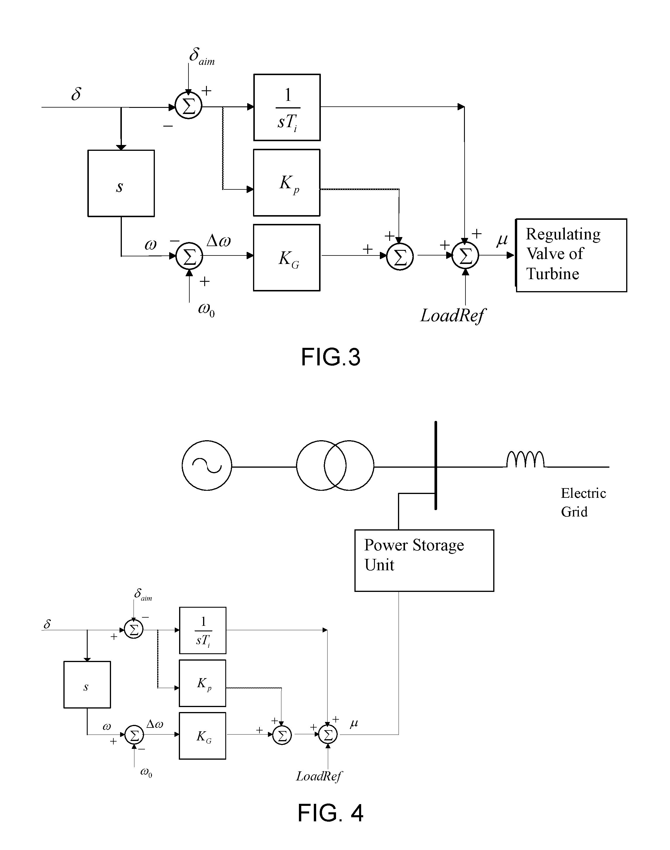
[0019]According to the method and system for eliminating low frequency oscillation between generators of the present invention, through the control of the absolute rotor angle of the power generator, the zero steady-state error control between the frequency and the rotor angle is realized. The position of the rotor of the power generator in the PPS determined rotating coordinate system is fixed (remain unchanged). The zero ste

Problems solved by technology

At present, after an electric power system is subjected to a disturbance, insufficient damping or negative damping may lead to oscillation of approximately equal amplitude or increased amplitude to occur in the rotor angle, the rotating speed of the power generator and the related electrical quantities (such as the power flow on transmission lines, the bus voltages, etc.).
After the power grids

Method used


Image

  • Method and System for Eliminating Low Frequency Oscillation Between Generators
  • Method and System for Eliminating Low Frequency Oscillation Between Generators
  • Method and System for Eliminating Low Frequency Oscillation Between Generators

Examples


Embodiment Construction

[0027]The preferred embodiment of the present invention is further described fully with the accompanying drawings as follows in which the exemplary embodiments of the present invention is described. The followings content will, with the help of the accompanying drawings of the embodiments of the present invention, clearly and fully describe the technological features of the embodiments of the present invention. Obviously, the following drawings description includes the illustrative embodiments for the present invention and is exemplary only. One skilled in the art in the present field of invention, without the need of inventiveness and diligent, can derive additional drawings based on the drawings of the present invention.

[0028]In recent years, with the development of measurement technology in synchronized phasor measurement unit (PMU), the technology of precise measurement of rotor angle in power generator, which refers to the angle of the Q-axis of the generator rotor in a rotatin...


PUM


Abstract

A method and system for eliminating the low-frequency oscillation between generators. By way of measuring the absolute rotor angle of a generator and controlling the rotor rotational speed, the absolute rotor angles obtained through measurement are the same when each GPS pulse per second signal arrives. The absolute rotor angles are angles of the internal potential Eq of the generator leading a GPS reference vector. Through the absolute rotor angle, zero steady state error control of the frequency and the rotor angle is achieved and the position of the generator rotor can remain unchanged in the PPS determined rotating coordinate system, thus suppressing the low-frequency oscillation better even without the need of remote measurement and achieving automatic local balance of active power during variation of loads. Accordingly, the power fluctuation on transmission lines is decreased while safe and stable operation of a large-scale interconnected power grid is achieved.

Description

CROSS REFERENCE OF RELATED APPLICATION[0001]This is a national phase national application of an international patent application number PCT / CN2014 / 081930 with a filing date of Jul. 10, 2014, which claimed priority of one foreign application which is filed in China: application number 201310321108.6 and filing date Jul. 20, 2013. The contents of these specifications, including any intervening amendments thereto, are incorporated herein by reference.BACKGROUND OF THE PRESENT INVENTION[0002]1. Field of Invention[0003]The present invention relates to technologies in operation and control of electric power system, and more particularly to method and system for eliminating low-frequency oscillation between generators.[0004]2. Description of Related Arts[0005]At present, after an electric power system is subjected to a disturbance, insufficient damping or negative damping may lead to oscillation of approximately equal amplitude or increased amplitude to occur in the rotor angle, the rotati...

Claims


Application Information

Patent Timeline
IPC IPC(8): H02P9/10
CPCH02P9/105H02M1/12H02P21/05Y02E60/00Y04S10/00Y04S10/22Y02E40/70H02J3/241H02J3/242
Inventor WEI, QIANGGUO, WEIMIN
Owner WEI QIANG
Why Eureka
Try Eureka