
Network consolidation by means of virtualization

Active Publication Date: 2016-06-09
NOKIA SOLUTIONS & NETWORKS OY
View PDF5 Cites 23 Cited by
  • Summary
  • Abstract
  • Description
  • Claims
  • Application Information

AI Technical Summary

Benefits of technology

This patent describes a new invention that has advantages over existing technologies. These advantages may include improved efficiency, enhanced functionality, or better performance.

Problems solved by technology

Due to their complexity their numbers are limited per network so that there are a few crucial topological points in the network which are single points of failure and which may become performance bottlenecks as traffic increases significantly (200 times in 10 years).
However, the edge nodes (e.g. GGSN, BRAS), due to their ambiguous nature (control and data forwarding) cannot be simply virtualized following pure data center principles—in pure IT data center setups there are no nodes that have this gateway function—thus data center technologies yet do not provide a suitable solution for gateway virtualization.
But without virtualization of these edge nodes the virtualization of the mobile core remains unfinished, deficient and crippled—the full potential of network virtualization can not be applied.
As there may be many of them, typically, a key issue is on performance rather than on complexity.
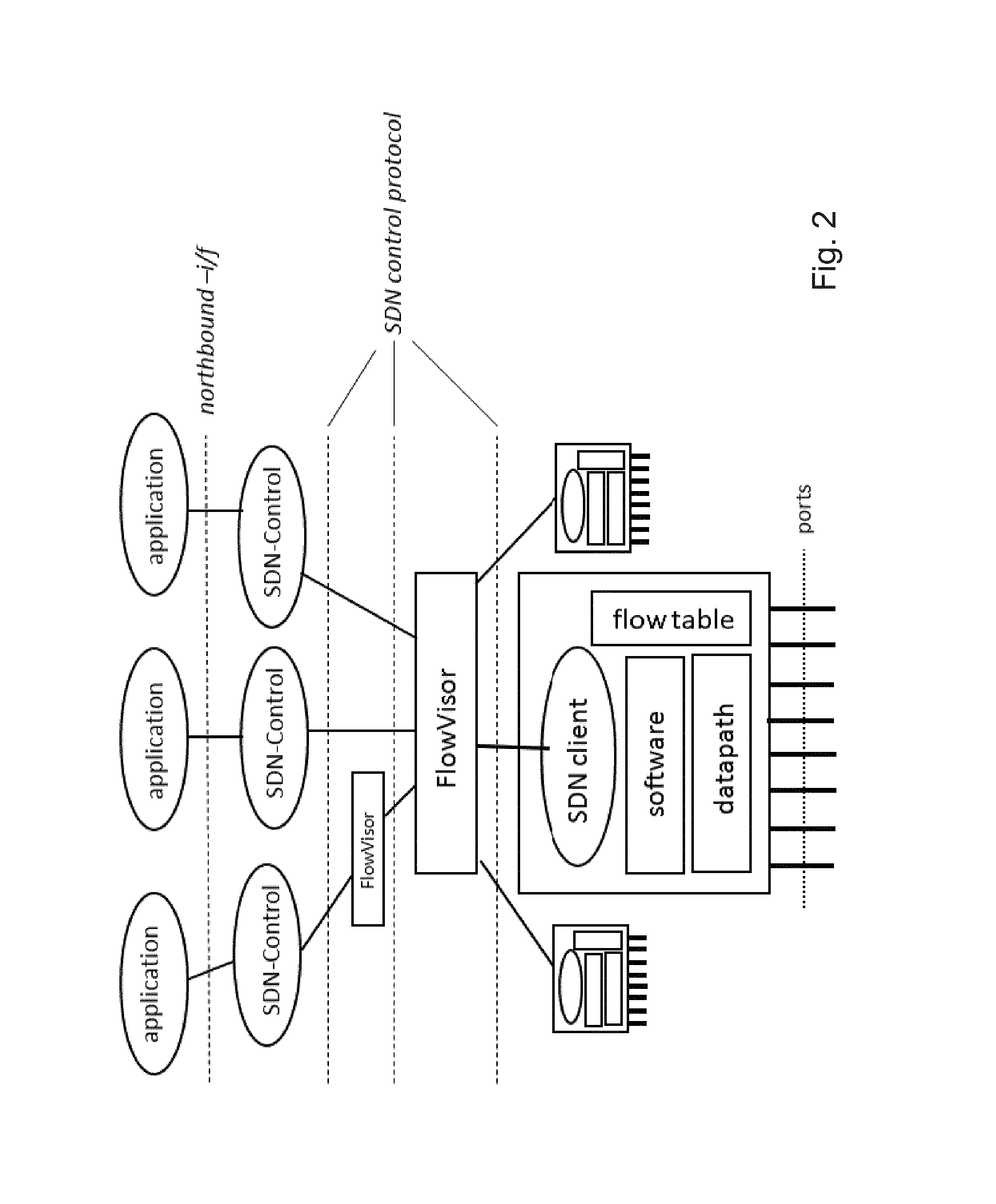
NEs and controller can be cascaded and access can be limited.
This is a typical deployment scenario for SDN enabled nodes and here the dilemma of this approach becomes obvious: the separation into control and data forwarding made the NE turn into a stone stupid forwarding engine that only allows relaying data packets from one port to another without further manipulation.
This may be well suitable for pure transport packet transmission but not for relaying transport user data information that require specific interworking on the forwarding plane.
Current SDN concepts do not properly address these issues.

Method used


Image

  • Network consolidation by means of virtualization
  • Network consolidation by means of virtualization
  • Network consolidation by means of virtualization

Examples


Embodiment Construction

[0133]Herein below, certain embodiments of the present invention are described in detail with reference to the accompanying drawings, wherein the features of the embodiments can be freely combined with each other unless otherwise described. However, it is to be expressly understood that the description of certain embodiments is given for by way of example only, and that it is by no way intended to be understood as limiting the invention to the disclosed details.

[0134]Moreover, it is to be understood that the apparatus is configured to perform the corresponding method, although in some cases only the apparatus or only the method are described.

[0135]As shown hereinabove, a network element, such as an edge node (GGSN, SecGW, RNC, BRAS, etc.) but not limited to edge nodes, may be decomposed either according to SDN (service chaining), or according to A-C-F separation. In detail, each function of the respective network element may be embodied as a separate entity as according to service c...


PUM


Abstract

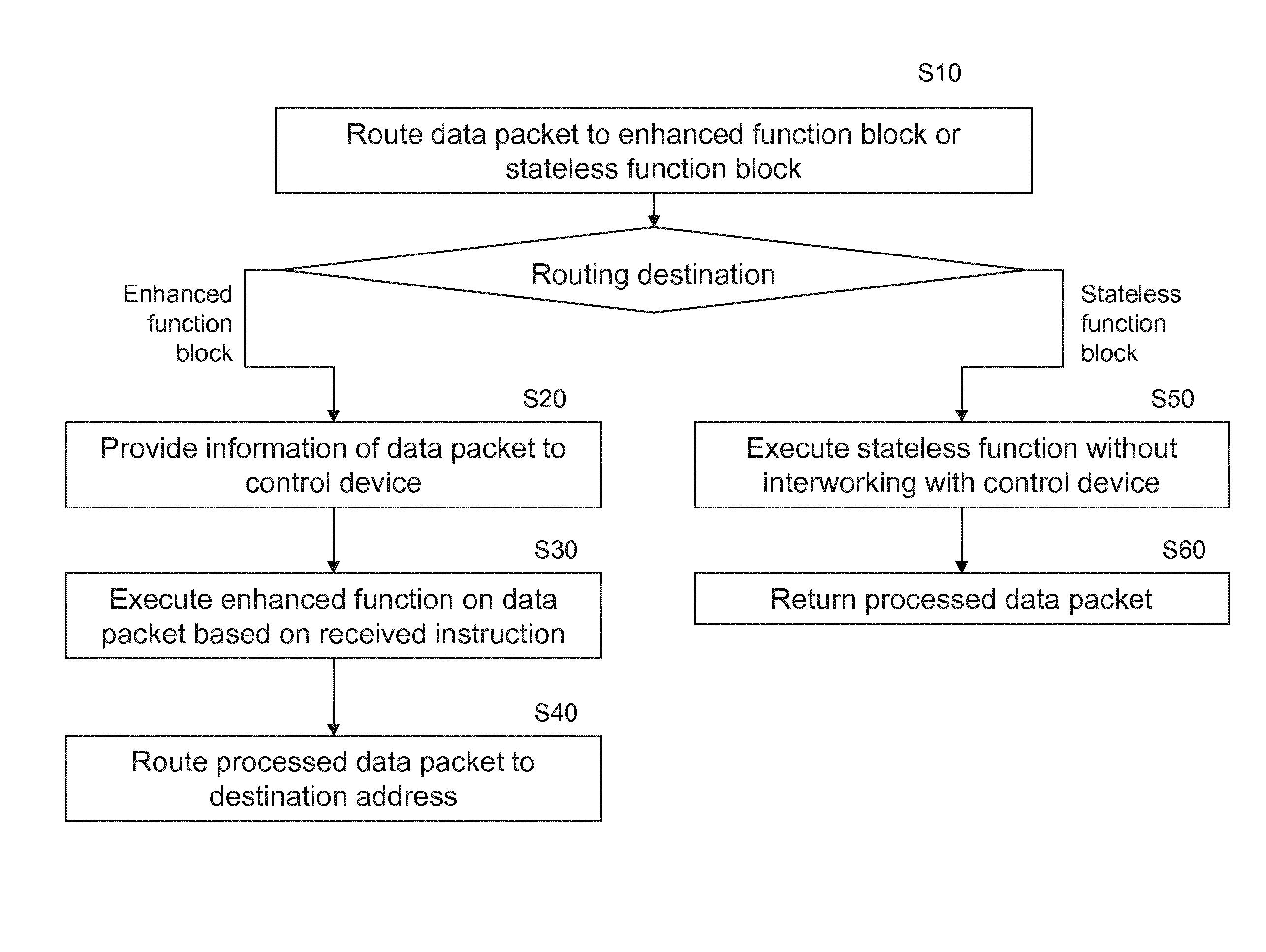
An apparatus, comprising an enhanced function block and a stateless function block; main routing means for routing, based on a header of a data packet and an incoming port, the data packet to one of the enhanced function block and the stateless function block; wherein the enhanced function blocks comprises providing means for providing an information comprised in the data packet to a control device; an enhanced function means for executing an enhanced function on the data packet to obtain a first processed data packet addressed to a destination address, wherein the enhanced function is based on an instruction for the data packet received in response to the provided information; and a first routing means for routing the first processed data packet to the destination address; and the stateless function blocks comprises a stateless function means for executing a stateless function on the data packet, wherein the stateless function is not based on an instruction for the data packet received in response to providing information comprised in the data packet to a control device, in order to, thus, obtain a second processed data packet; and returning means for returning the second processed data packet to the main routing means.

Description

FIELD OF THE INVENTION[0001]The present invention relates to an apparatus, a method, and a computer program product related to virtual network architecture.BACKGROUND OF THE INVENTION[0002]FIG. 3 shows the basic architecture of a mobile network. In a simplified view, a mobile network comprises of five domains:[0003]User Equipment UE. Those may range from simple cellular mobile phones over smart phones to wireless notebooks[0004]Radio Access Network RAN comprising of base stations, antennas, everything that is there to provide radio access[0005]Mobile Core. This includes facilities necessary to handle user authentication and authorization, where user subscription data is stored (HSS home subscriber system)[0006]Service Delivery Framework SDF. This comprises of servers for mobile operator content and services including content delivery functions like cashing.[0007]Backend System. Here are the network management facilities and billing and charging systems.[0008]In addition, there are t...

Claims


Application Information

Patent Timeline
IPC IPC(8): H04L29/06H04L12/715H04L12/741H04L45/74
CPCH04L63/0245H04L45/74H04L63/10H04L63/0281H04L45/64H04L45/54H04L63/0272H04L63/08H04L12/1407
Inventor HOFFMANN, MARCOMORPER, HANS-JOCHEN
Owner NOKIA SOLUTIONS & NETWORKS OY
Learn More