Methods and Devices for Removal of Thromboembolic Material

a technology of thromboembolic material and thromboembolic fluid, which is applied in the field of medical devices, can solve the problems of insufficient effectiveness of current available therapies, limited treatment options for ich, and long association with high morbidity and mortality, so as to facilitate the removal of thromboembolic material, prevent small emboli dislocation, and minimize additional blood loss

Active Publication Date: 2016-06-16
PENUMBRA
View PDF2 Cites 69 Cited by
  • Summary
  • Abstract
  • Description
  • Claims
  • Application Information

AI Technical Summary

Benefits of technology

[0052]In another embodiment, irrigation is provided at least partially around the rotational member and within the aspiration lumen to further facilitate the removal of thromboembolic material.
[0053]In yet another embodiment, additional aspiration is provided proximally to the treatment area via an additional catheter or guiding catheter to further prevent small emboli dislodgment during the removal of blood clots and other tissue.
[0054]In another embodiment, the aspiration catheter and the rotational member are configured to deliver radiofrequency energy for blood vessel or tissue cauterization when necessary. Occasionally, during the removal of thromboembolic material from outside of the endovascular space such as ICH, additional bleeding may occur. Such bleeding is often caused by bleeding of non-effected vessels from the original bleed or from re-bleeding from the affected vessels. This new bleeding may cause another hemorrhagic stroke. To minimize additional blood-loss and prevent exsanguination, a cauterizing approach may be used, including but not limited to electro cautery, ultrasound cautery and chemical cautery. Electro-cauterization is preferable to other forms of cauterization because it will not leach into neighboring tissue and cauterize outside of the intended boundaries.

Problems solved by technology

ICH has long been associated with high rates of morbidity and mortality.
Treatment choices for ICH are limited, and the effectiveness of currently available therapies is inadequate.
Endovascular and outside of endovascular thromboembolic disease remain very widespread causes of death and disability with no ideally effective treatment currently available.
Often, catheters used to remove clots from brain arteries get clogged after partial removal of clots even under absolute vacuum.

Method used


Image

  • Methods and Devices for Removal of Thromboembolic Material
  • Methods and Devices for Removal of Thromboembolic Material
  • Methods and Devices for Removal of Thromboembolic Material

Examples


Embodiment Construction

[0080]The following detailed description is of the best presently contemplated modes of carrying out the invention. This description is not to be taken in a limiting sense, but is made merely for the purpose of illustrating general principles of embodiments of the invention. The scope of the invention is best defined by the appended claims.

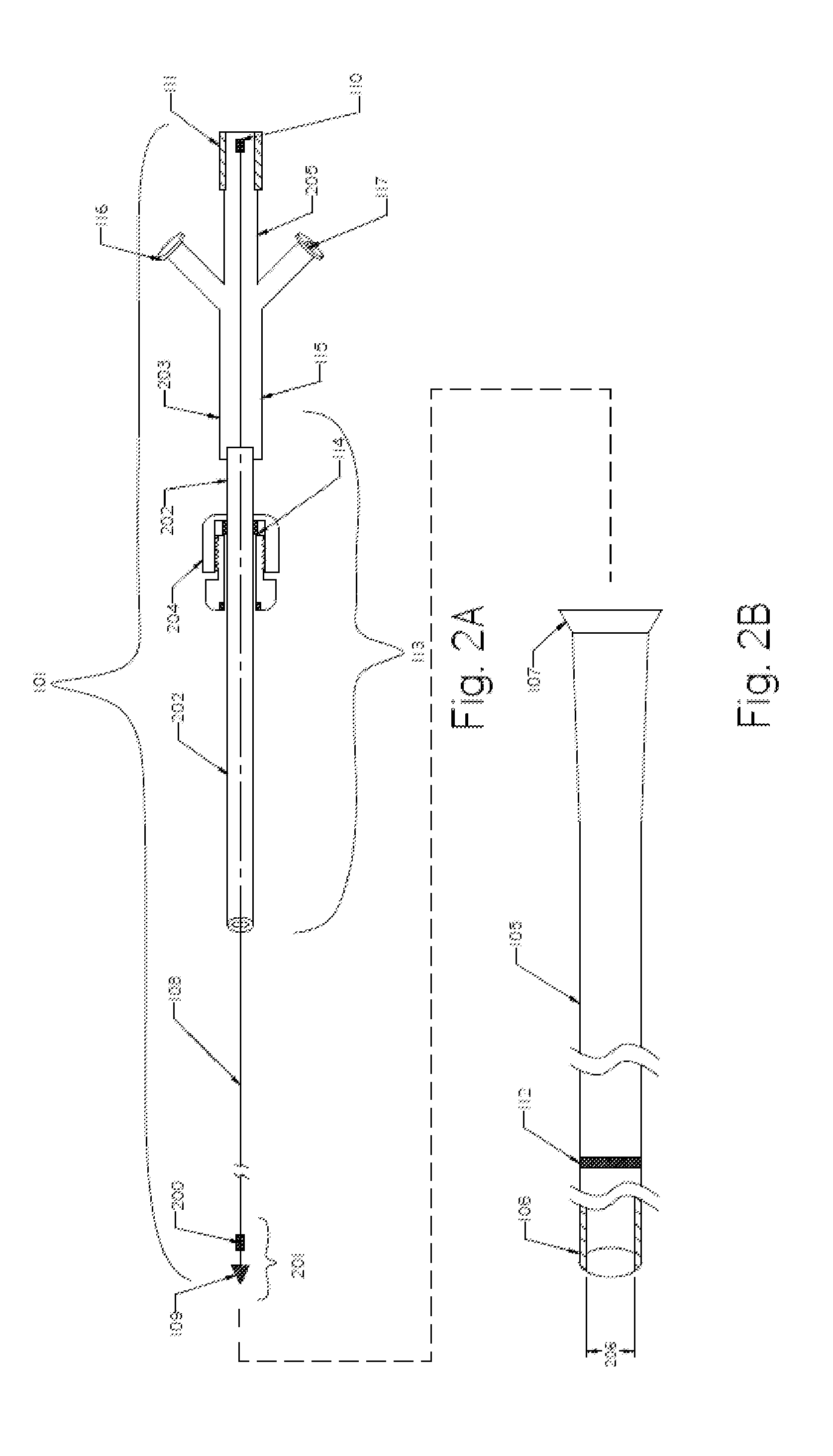
[0081]As used herein, “rotational member”, “cable”, “cable shaft”, “rotating member” all refer to the mechanical power-transmission devices used to transmit rotary motion through a straight treatment access, as well as through bends and curves

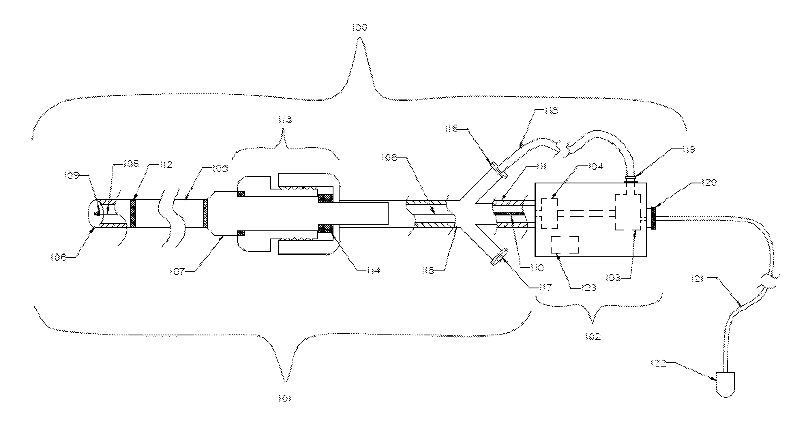
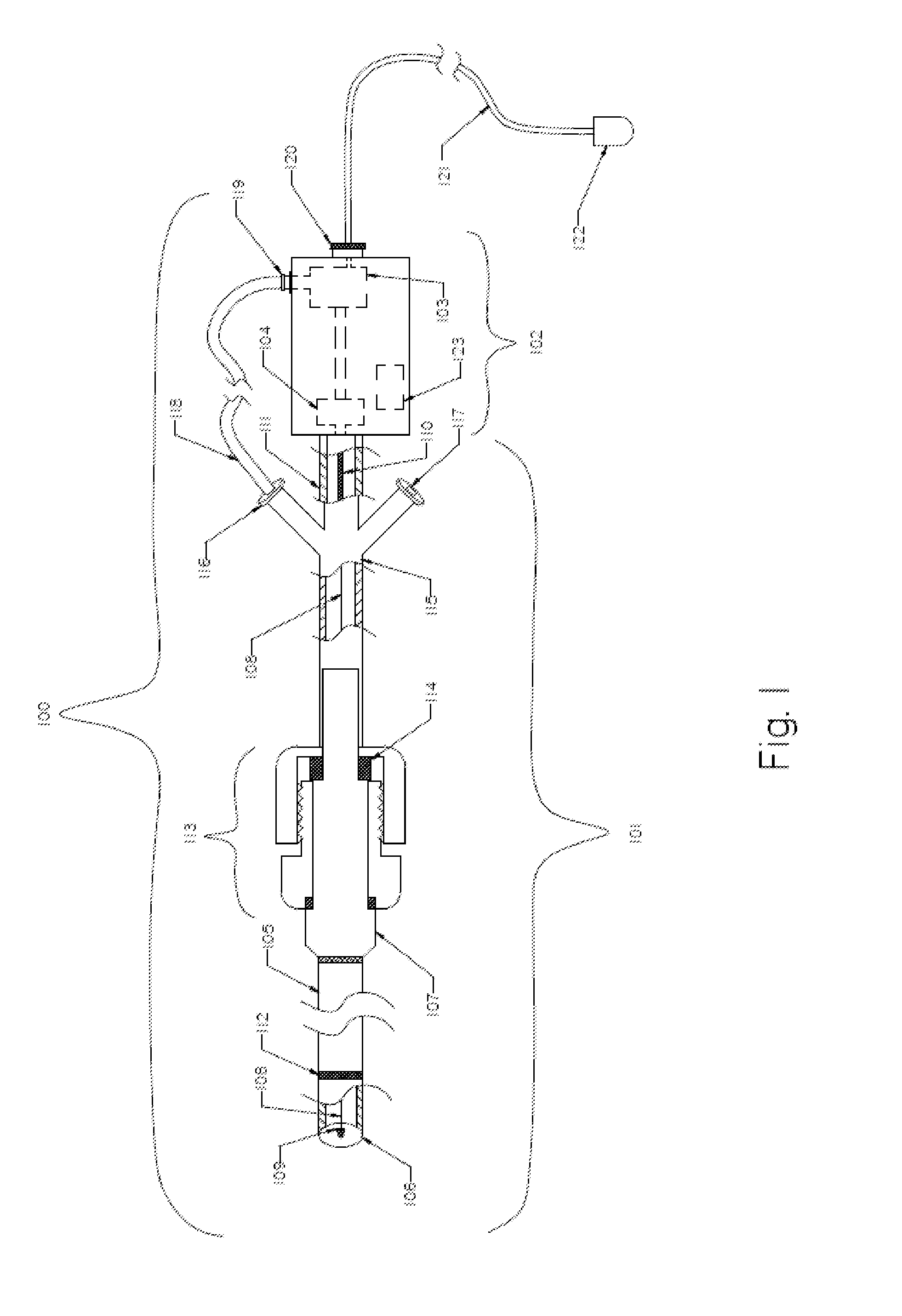
[0082]FIG. 1 illustrates an exemplary embodiment of a thromboembolic removal system 100. The thromboembolic removal system 100 includes two major components: the extraction device 101 and the drive unit 102. The drive unit 102 includes at least one vacuum pump 103 to aspirate thromboembolic material, and an electrical motor 104. The main components of the extraction device 101 include an aspiration catheter 1...


PUM


Abstract

Methods and devices to remove thromboembolic material from the human body using rotational energy and aspiration are disclosed. A thromboembolic removal system includes an extraction device and drive unit. The extraction device is introduced to the treatment area and activated by the drive unit to separate, break apart, loosen or soften thromboembolic material and to facilitate its aspiration outside the patient.

Description

RELATED CASES[0001]This application claims priority to U.S. Provisional Application No. 62 / 124,406, filed on Dec. 16, 2014, and is a continuation-in-part of co-pending application Ser. No. 14 / 668,622, filed Mar. 25, 2015, whose entire disclosure is incorporated herewith as though fully set forth herein.BACKGROUND OF THE INVENTION[0002]1. Field of the Invention[0003]The field of the present application pertains to medical devices. More specifically, the present application is related to devices and methods for removal of thromboembolic obstructing matter from the human endovascular system, including cerebral arteries and other parts of the human body.[0004]2. Description of the Prior Art[0005]Arterial and venous thromboembolic disease remains a major cause of death and disability despite the discovery of heparin by McLean and Howell in 1916 and its subsequent introduction into clinical practice in 1936. Each year, acute limb ischemia affects 14 persons per 100,000 in the United State...

Claims


Application Information

Patent Timeline
Patent Type & Authority Applications(United States)
IPC IPC(8): A61B17/22A61M25/10A61M1/00A61B17/3207
CPCA61B17/22A61B17/320758A61B2017/22079A61M1/0082A61B2017/22001A61M25/104A61B18/1492A61B2017/22067A61B2017/22078A61B2017/320775A61B2018/00208A61B2217/005A61B2218/007
Inventor NITA, HENRY
Owner PENUMBRA
Why Eureka
Try Eureka