Aircraft fuel deoxygenation system

a fuel system and aircraft technology, applied in liquid degasification, separation processes, lighting and heating apparatuses, etc., can solve the problems of reducing the efficiency of the fuel system, limiting the ability of the fuel to absorb heat beyond, and thermal degradation, so as to increase the fuel/gas, improve the deoxygenation efficiency, and increase the deoxygenation drive potential

Active Publication Date: 2016-06-16
HONEYWELL INT INC
View PDF1 Cites 48 Cited by
  • Summary
  • Abstract
  • Description
  • Claims
  • Application Information

AI Technical Summary

Benefits of technology

[0018]It will additionally be appreciated that in some embodiments, such as the one depicted in FIG. 1, the system 100 may additionally include a heat exchanger 115 and a fuel filter 117 between the boost pump 102 and the contactor-separator 104. The heat exchanger 115 is coupled to receive the fuel / gas mixture from the pump 102 and a fluid from a non-illustrated fluid source. The fluid and fluid source may vary, but in one embodiment the fluid is lubricant, such as oil, supplied from a non-illustrated gas turbine engine. In such embodiments, the heat exchanger functions as a fuel heater / oil cooler. Regardless, the heat exchanger 115 is configured to transfer heat from the fluid to the fuel / gas mixture to thereby increase fuel / gas mixture temperature prior to supplying the fuel / gas mixture to the contactor-separator 104, to thereby increase the deoxygenation drive potential and improve deoxygenation efficiency.
[0019]The fuel filter 117 is coupled between the heat exchanger 115 and the contactor-separator 104. The fuel filter 117 is configured to remove particulate from the fuel / gas mixture, and break up inert gas bubbles in the fuel / gas mixture into relatively smaller sized bubbles. This latter function will improve the efficiency of the downstream deoxygenation processes.
[0020]Whether or not the system 100 includes the heat exchanger 115 and / or the fuel filter 117, the contactor-separator 104 is coupled to receive the fuel / gas mixture and is configured to implement the functions of both a contactor and a separator. In some embodiments, as depicted in FIG. 1, the contactor-separator 104 may also receive inert gas from the inert gas source 112. As is generally known, a contactor functions to intensify the mass-transfer of dissolved oxygen to the inert gas by maximizing the contact surface between the fuel and inert gas, and to providing further mixing of the fuel and inert gas to thereby facilitate efficient mass transfer. A separator functions to separate the deoxygenated fuel and the inert gas / oxygen purge gas that is generated. Thus, the contactor-separator 102, upon receipt of the fuel / gas mixture and, in some embodiments, the inert gas, removes a significant portion of the oxygen from the fuel and thereby generates and supplies deoxygenated fuel (e.g., <2-6% oxygen) and purge gas. The deoxygenated fuel is supplied to the centrifuge-separator pump 106, and the purge gas is directed overboard via an overboard control valve 116, or is directed to a gas pump 118 (described further below), or both.

Problems solved by technology

The presence of molecular oxygen or entrained air limits the ability of fuel to absorb heat beyond approximately 300° F. without undergoing deleterious thermal degradation.
Thermal degradation often appears as solid materials which adhere to surfaces and degrades fuel system performance.
However, these often use equipment that is subject to fouling, which can lead to increased maintenance, and / or process steps that are difficult to control.

Method used


Image

  • Aircraft fuel deoxygenation system
  • Aircraft fuel deoxygenation system
  • Aircraft fuel deoxygenation system

Examples


Embodiment Construction

[0015]The following detailed description is merely exemplary in nature and is not intended to limit the invention or the application and uses of the invention. As used herein, the word “exemplary” means “serving as an example, instance, or illustration.” Thus, any embodiment described herein as “exemplary” is not necessarily to be construed as preferred or advantageous over other embodiments. All of the embodiments described herein are exemplary embodiments provided to enable persons skilled in the art to make or use the invention and not to limit the scope of the invention which is defined by the claims. Furthermore, there is no intention to be bound by any expressed or implied theory presented in the preceding technical field, background, brief summary, or the following detailed description.

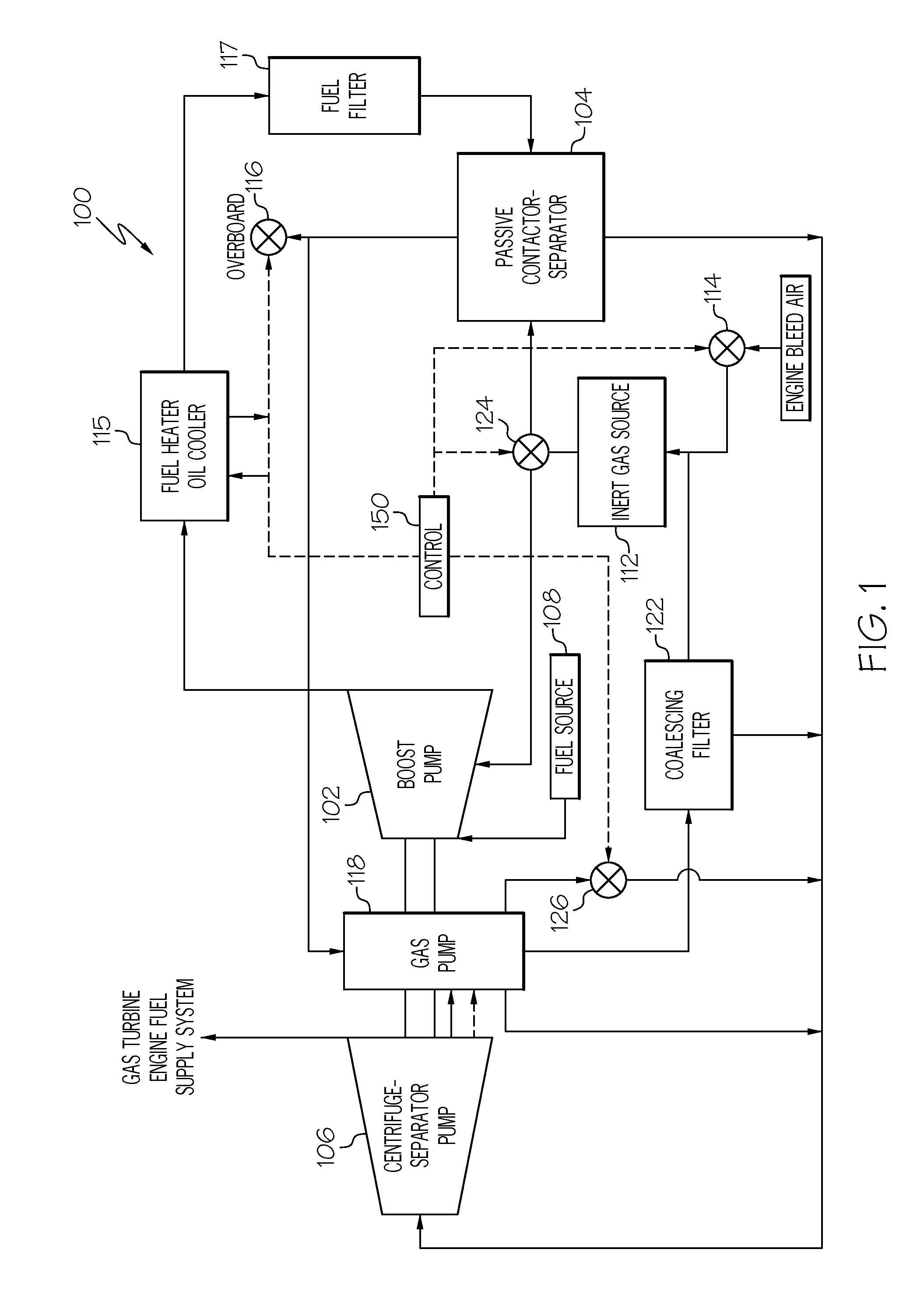
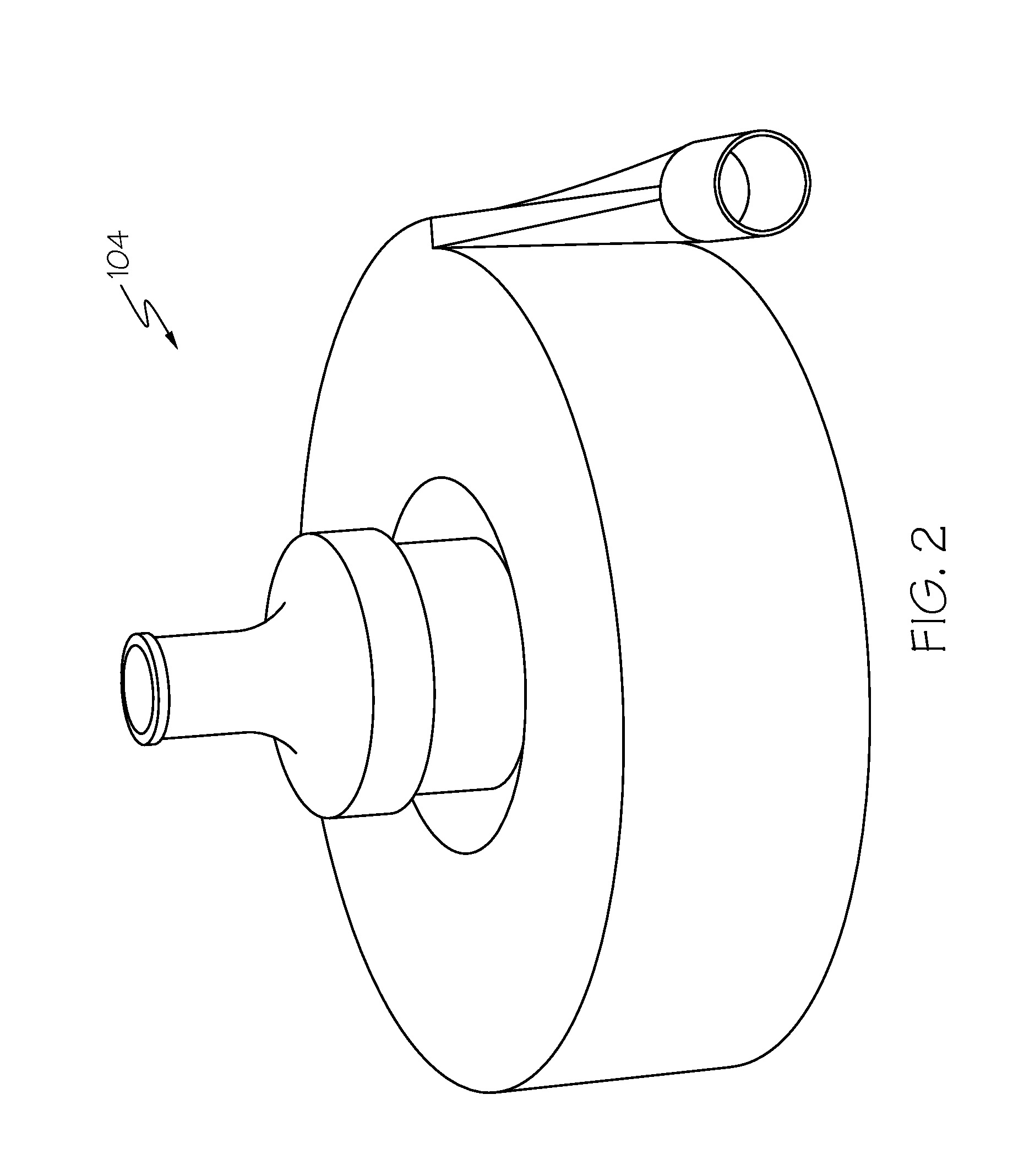
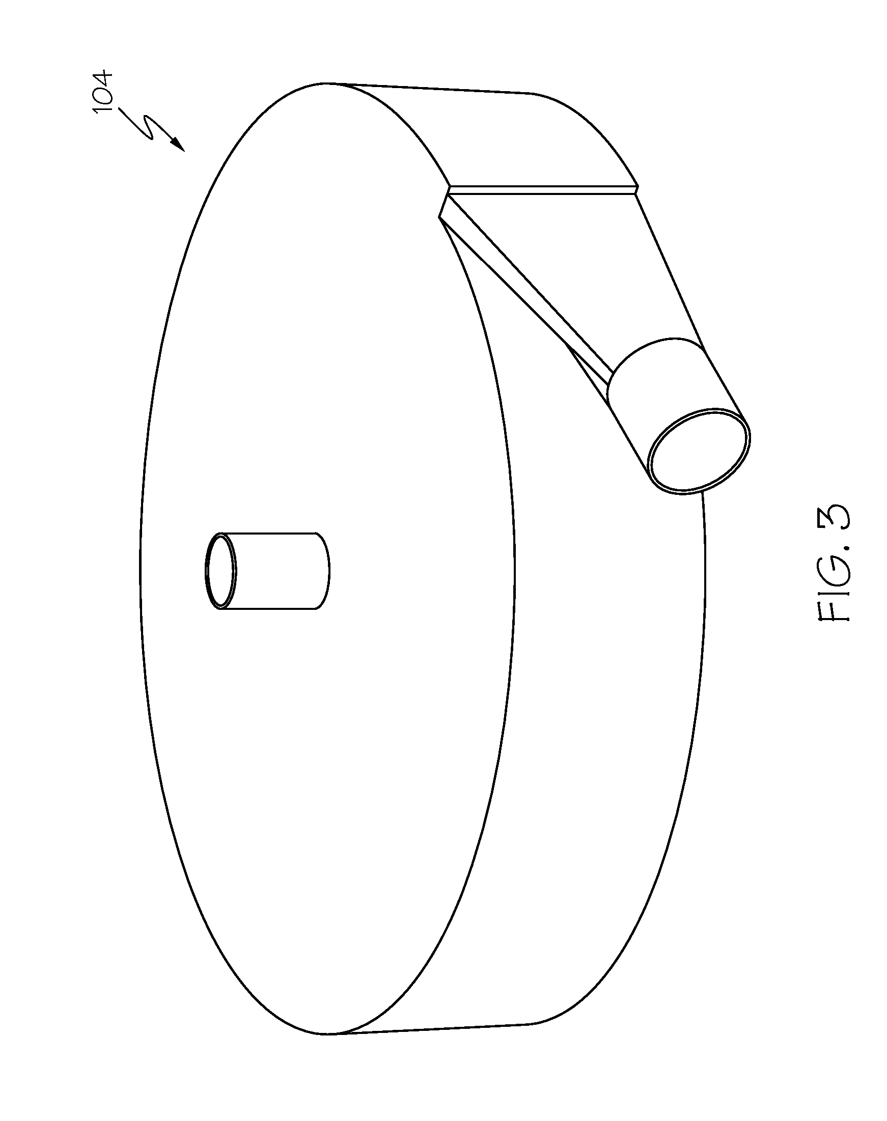
[0016]Referring first to FIG. 1, an embodiment of an aircraft fuel deoxygenation system 100 is depicted. The depicted system 100 includes at least a boost pump 102, a contactor-separator 104, a...


PUM

PropertyMeasurementUnit
temperatureaaaaaaaaaa
thermal energyaaaaaaaaaa

Abstract

An aircraft fuel deoxygenation system includes a boost pump, a contactor-separator, and a centrifuge-separator pump. The boost pump is adapted to receive fuel from a fuel source and inert gas from an inert gas source, and is configured to mix the fuel and inert gas and supply a fuel/gas mixture. The contactor-separator is coupled to receive the fuel/gas mixture and is configured to remove oxygen from the fuel and thereby generate and supply deoxygenated fuel with entrained purge gas and separated purge gas. The centrifuge-separator pump is coupled to receive the deoxygenated fuel with entrained purge gas and is configured to separate and remove the entrained purge gas from the deoxygenated fuel and supply the deoxygenated fuel and additional purge gas.

Description

TECHNICAL FIELD[0001]The present invention generally relates to fuel deoxygenation, and more particularly relates to systems for deoxygenating aircraft fuel.BACKGROUND[0002]Modern aircraft rely on efficient heat sink options for thermal management. The jet fuel that is supplied to the propulsion engines is often a convenient sink for excess thermal energy, and the energy is efficiently retained in the engine thermodynamic cycle. The presence of molecular oxygen or entrained air limits the ability of fuel to absorb heat beyond approximately 300° F. without undergoing deleterious thermal degradation. Thermal degradation often appears as solid materials which adhere to surfaces and degrades fuel system performance. Moreover, wetted surfaces comprised of metallic materials can further catalyze the reaction of oxygen with fuel and subsequent formation of carbonaceous, coke-like material.[0003]It is possible to substantially reduce coke-based fuel degradation by removing oxygen from the f...

Claims


Application Information

Patent Timeline
Patent Type & Authority Applications(United States)
IPC IPC(8): B64D37/34B01D35/02B01D46/00B01D19/00
CPCB64D37/34B01D19/0047B01D19/0005B01D46/00B01D19/0057B01D35/02B01D19/0068F23K2900/05082
Inventor LO, CHARLESBLUMER, ERICLABODA, DANBERSHITSKY, ALEXANDER
Owner HONEYWELL INT INC
Why Eureka
Try Eureka