Apparatus for drilling deeper and wider well bore with casing

a technology of casing and well bore, which is applied in the direction of drilling with mechanical conveying, borehole/well accessories, insulation, etc., can solve the problems of limitations of existing technologies relevant to the depth and diameter of well bor

Active Publication Date: 2016-06-16
LAKIC NIKOLA
View PDF0 Cites 13 Cited by
  • Summary
  • Abstract
  • Description
  • Claims
  • Application Information

AI Technical Summary

Benefits of technology

[0016]Diameter of the excavation line and rate of flow of mud and cuttings through it and diameter of the fluid delivery line and rate of fluid flow through it are in balance requiring only limited fluid column at the bo...

Problems solved by technology

Accordingly, existing technologies have limitations relevant to the depth and diameter of the well ...

Method used


Image

  • Apparatus for drilling deeper and wider well bore with casing
  • Apparatus for drilling deeper and wider well bore with casing
  • Apparatus for drilling deeper and wider well bore with casing

Examples


embodiment 200

[0125]FIG. 14 illustrates an enlarged cross sectional view taken along line 14-14′ of FIG. 18 of an in-ground motorized drill head 21 of an alternative embodiment 200 for drilling faster, deeper and wider well bore, explained in FIG. 13. The in-ground motorized drill head 21 consist of the same major elements explained earlier in motorized drill head 20. In this embodiment deviation control mechanism (system) 120 is located at the top of motorized drill head 21 (illustrated and explained in FIG. 19). In this embodiment there is no a hydraulic control mechanism for providing vertical sliding motion of the peripheral rotor 44 and peripheral drill bit 32.

[0126]FIG. 15 is a cross sectional view taken along line 15-15′ of FIG. 14 of an in-ground motorized drill head 21. Here in FIG. 15 is illustrated drill bit 32 with three recesses 28 which forms a three-teethed peripheral drill bit 32. Also, here are illustrated collecting chamber 10 formed between extended wall 45 of the cylinder 49 o...

embodiment 360

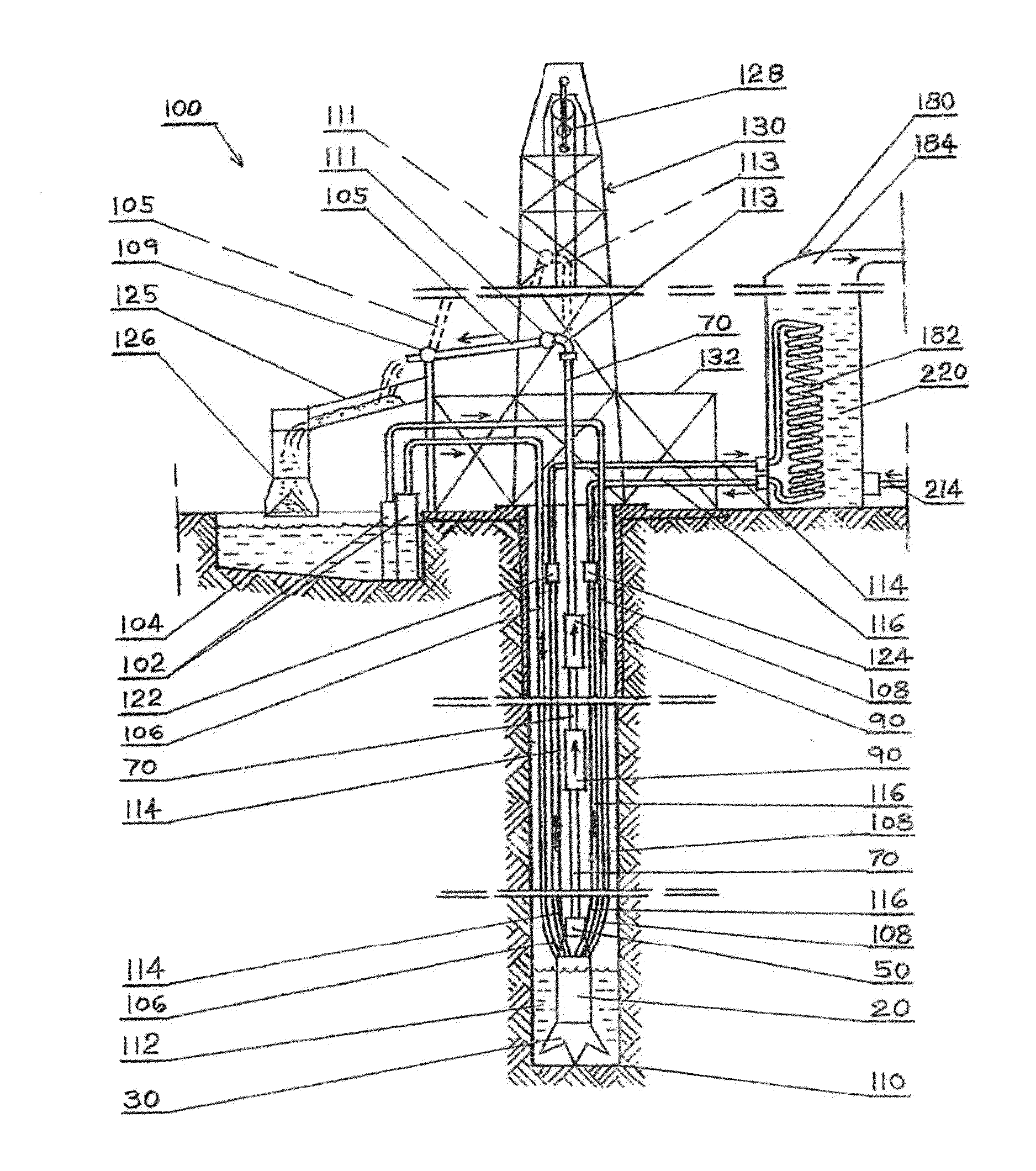
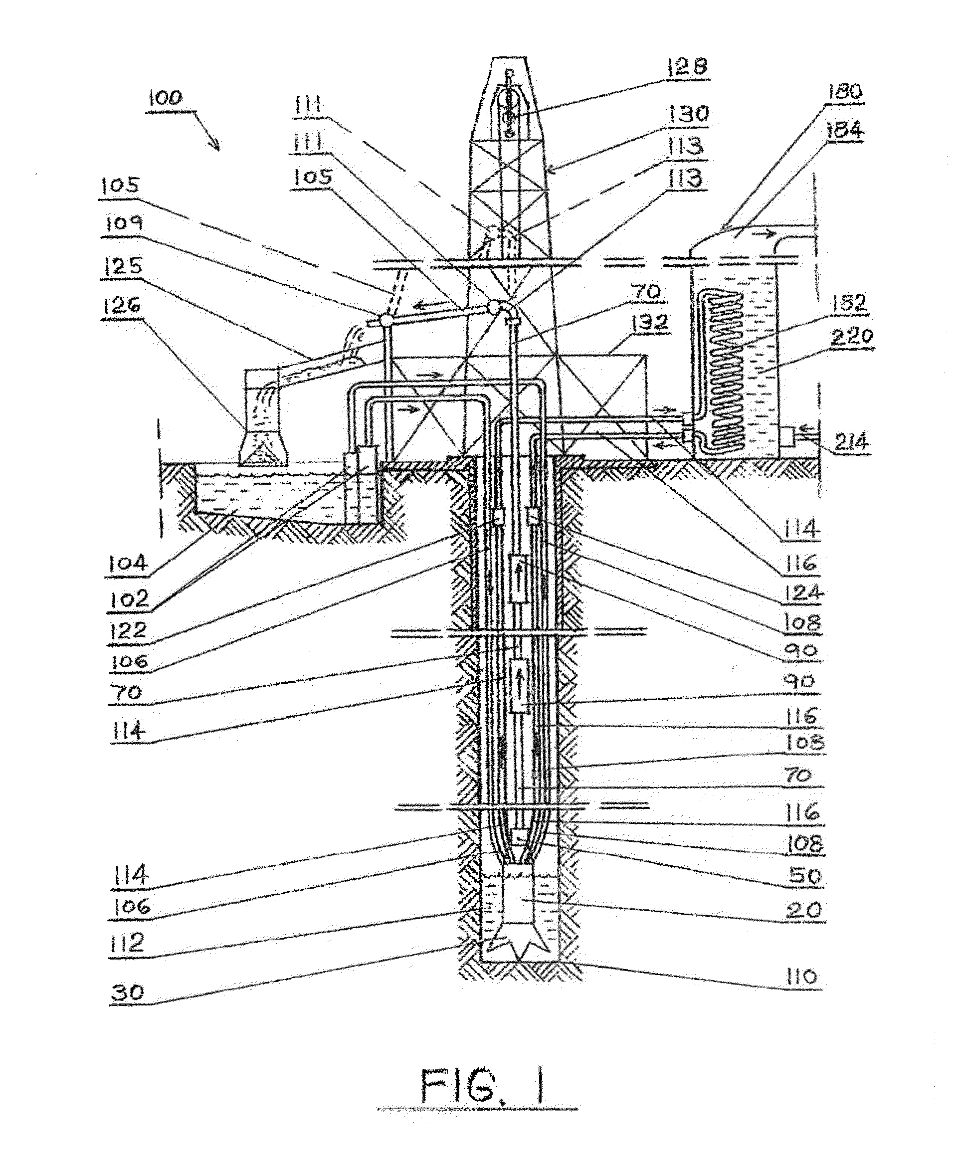
[0174]FIG. 43 is a schematic diagram and cross sectional view of embodiment 360 which include a circular cage (elevator) 400 used for building casing of the wellbore explained in FIG. 42 and also used for disassembly of the drilling apparatus after drilling process is completed. Here is shown excavation line 370 as a compact assembly which incorporates In-line-Pump 90, fluid delivery line 106 and 108 and close loop engine cooling line 114 and 116. Here is also shown an additional element of this invention a motorized circular cage (elevator) 400 with an expendable section 412 for delivering and installing metal sheets and concrete for casing of the wellbore during drilling process. Also, shown here is a Blow Out Preventer 31. Also, show is a hoisting line composed of wound steel cable 402 spooled over a revolving reel. More details about this system will be explained in following illustrations. Here is also shown box with electronics and sensors 488 attached to motorized drill head ...


PUM


Abstract

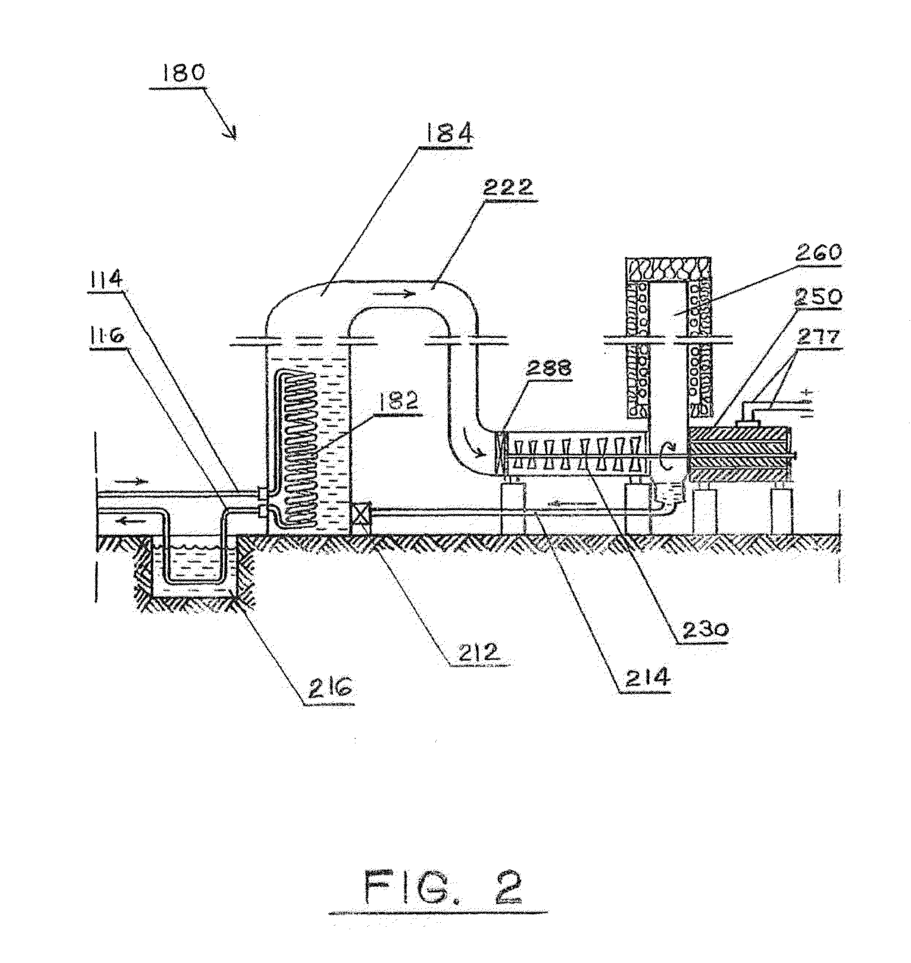
An apparatus and method for drilling deeper and wider well bores is provided. The apparatus includes a motorized drill head for cutting and shredding ground material; a separate excavation line; a separate fluid delivery line; a separate close loop engine cooling line; and a casing system. Excavation line includes repetitive stationary segments of the main pipe with periodical segments of an in-line excavation pump. The close loop cooling line includes a heat exchanger in the motorized drill head and in the in-line excavation pump and one on the ground surface in the binary unit where fluid is cooled and in process electricity produced. The diameter of the excavation line and rate of flow of mud and cuttings through it and the diameter of the fluid delivery line and rate of fluid flow through it are in balance requiring only limited fluid column at the bottom of the well bore.

Description

CROSS-REFERENCE TO RELATED APPLICATIONS[0001]The present application is a continuation-in-part of U.S. patent application Ser. No. 13 / 424,184, filed Mar. 19, 2012, currently pending, which is a continuation-in-part of PCT Application No. PCT / US2010 / 049532, filed Sep. 20, 2010, which claims priority to U.S. Provisional Application No. 61 / 276,967 filed Sep. 19, 2009, U.S. Provisional Application No. 61 / 395,235 filed May 10, 2010 and U.S. Provisional Application No. 61 / 397,109 filed Jun. 7, 2010 the contents of which are hereby incorporated entirely herein by reference.BACKGROUND[0002]1. Field of Invention[0003]The subject matter described herein generally relates to a drilling apparatus and related method, and more specifically to well bore drilling for an emerging technology such as “Self Contained In-Ground Geothermal Generators” (SCI-GGG) where drilling relatively deeper wells having a wider diameter and reduced drilling cost are applicable.[0004]2. Related Art[0005]Nearly all oil,...

Claims


Application Information

Patent Timeline
IPC IPC(8): E21B7/28
CPCE21B7/28E21B21/12E21B7/002E21B7/005E21B17/18E21B21/01E21B4/006E21B7/20E21B7/201E21B36/001
Inventor LAKIC, NIKOLA
Owner LAKIC NIKOLA
Why Eureka
Try Eureka