
Electric fireplace having humidifying device

Active Publication Date: 2016-06-16
LU MIN HSUN
View PDF3 Cites 19 Cited by
  • Summary
  • Abstract
  • Description
  • Claims
  • Application Information

AI Technical Summary

Benefits of technology

The present invention is an electric fireplace with a humidifying device that solves the shortcomings of prior art. The design is simple and the fireplace has multiple functions such as imitation of flame, air purification, and heating. Users can watch a realistic flame and inhale fresh but not dry warm wind. The humidifying device delivers water to the atomization plate through a cotton rod to generate atomized particles, providing a better user experience. The technical effects of the present invention are that it has a simple structure, is easy to produce and provides a better user experience compared to prior art.

Problems solved by technology

But, because the current environmental pollution is getting worse, people pay more attention to health.
When the humidity is too less, people's skin is dry, rough, and aging.
Sometimes, the lips are also dry or the throat is itching, or even it causes a sore throat, wheezing, etc.
If the air is too polluted, people breathe very uncomfortably and it may cause a variety of respiratory diseases.

Method used


Image

  • Electric fireplace having humidifying device
  • Electric fireplace having humidifying device
  • Electric fireplace having humidifying device

Examples


Embodiment Construction

[0017]Embodiments of the present invention will now be described, by way of example only, with reference to the accompanying drawings.

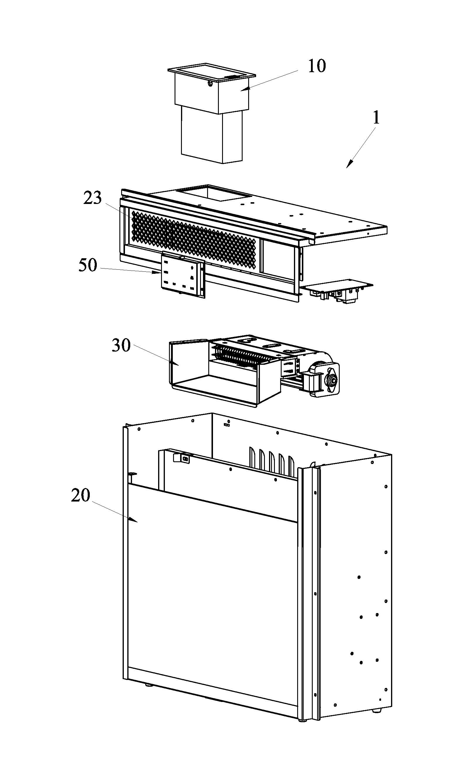
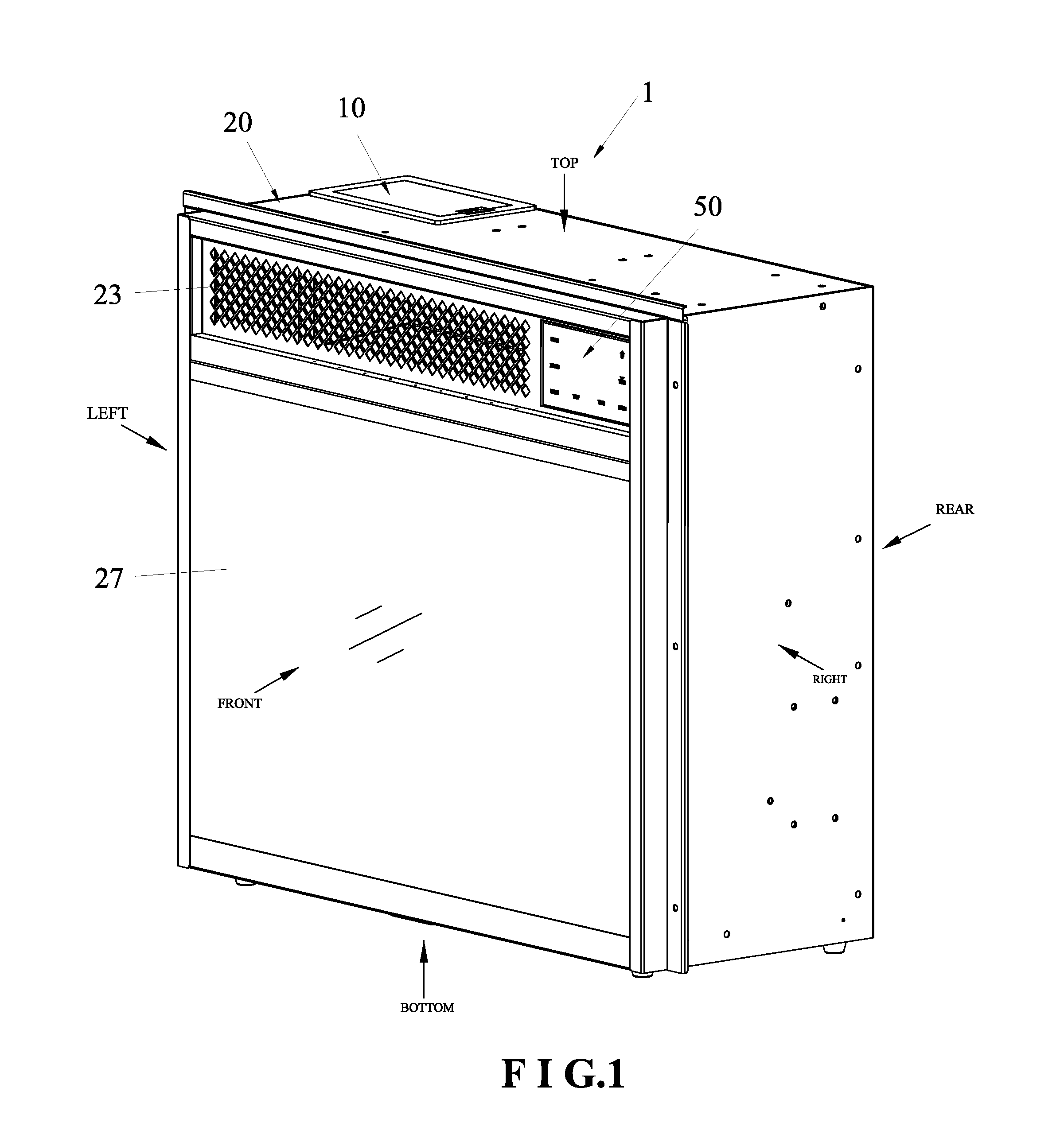
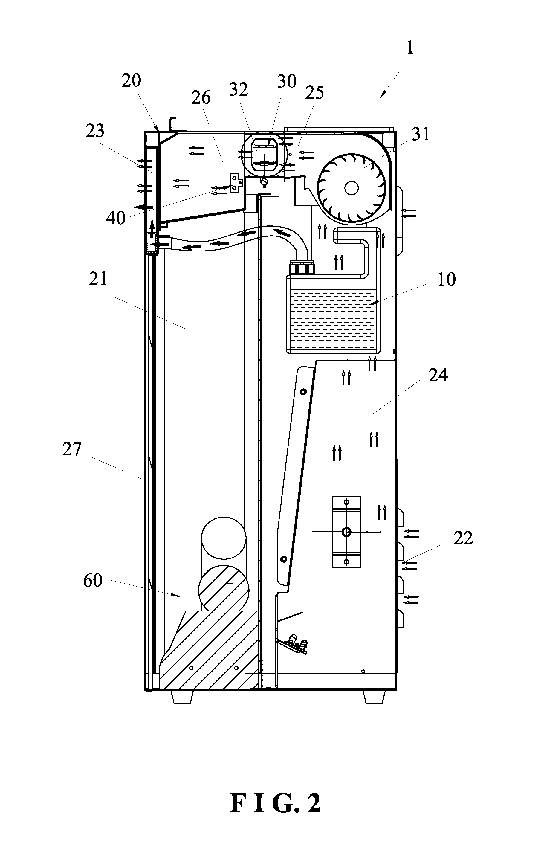
[0018]As shown in FIG. 1 to FIG. 6, the present invention discloses an electric fireplace 1 having a humidifying device 10. The humidifying device 10 is disposed in the electric fireplace 1 for the electric fireplace 10 to exhaust warm but not dry air. The electric fireplace 1 comprises a humidifying device 10, a casing 20, a heating device 30, an air purifying device 40, a touch control panel 50, and a flame imitation device 60.

[0019]As shown in FIG. 2, the casing 20 has an accommodation room 21 therein. The casing 20 has an air inlet 22 and an air outlet 23 thereon. The air inlet 22 is disposed at a rear side of the casing 20. The air outlet 23 is disposed at a front side of the casing 20. An air inlet passage 24, a heating passage 25, and an air purifying passage 26 are formed in sequence between the air inlet 22 and the air outlet 23. The front si...


PUM


Abstract

The present invention discloses an electric fireplace having a humidifying device. The electric fireplace includes a casing. A flame imitation device, a heating device, an air purifying device, the humidifying device, and a touch control panel are provided in the casing. The electric fireplace is combined with the flame imitation device, the air purifying device, and the heating device to provide multiple functions. The user can watch the realistic flame and inhale fresh but not dry warm wind. The humidifying device includes a water container, a cotton rod, a fixing knob, an atomization plate, a hollow pipe, and a fog output box. The humidifying device delivers the water to the atomization plate through the cotton rod to generate atomized particles. The present invention has a simple structure and can be produced easily.

Description

BACKGROUND OF THE INVENTION[0001]1. Field of the Invention[0002]The present invention relates to an electric fireplace, and more particularly to an electric fireplace having a humidifying device.[0003]2. Description of the Prior Art[0004]A conventional electric fireplace, as disclosed in CN1635305A, comprises a casing. The casing is provided with an electric heater and a flame imitation mechanism. The flame imitation mechanism comprises an imitation burning bed located at the front of a cavity of the casing, a flame image screen close to the back of the imitation burning bed, a light source at the rear of the casing, and a turning sleeve fitted on the light source. The surface of the turning sleeve is formed with a plurality of flame-shaped holes. The light of the light source inside the flame-shaped holes projects on the flame image screen to form a burning flame pattern. The turning sleeve is connected with a motor through a transmission mechanism.[0005]This conventional electric ...

Claims


Application Information

Patent Timeline
IPC IPC(8): F24D13/00A61L9/12F24F6/02
CPCF24D13/00A61L9/12F24F6/025F24F6/12
Inventor LU, WEILIN
Owner LU MIN HSUN
Learn More