Photonic Crystal Microsphere

a technology of crystal microspheres and microspheres, which is applied in the field can solve the problems of color pigments, difficult to achieve the effect of photonic crystal microspheres, and easy damage to periodic structures formed by mono-disperse particles, so as to achieve efficient large-scale production and improve mechanical strength

Active Publication Date: 2016-06-16
THE PROCTER & GAMBLE COMPANY +1
View PDF1 Cites 36 Cited by
  • Summary
  • Abstract
  • Description
  • Claims
  • Application Information

AI Technical Summary

Benefits of technology

[0006]It is an advantage of the present invention to provide a photonic crystal microsphere that enables a pure color (i.e., within a defined wavelength) across the full visible spectrum, without angle-dependency.
[0007]It is yet another advantage of the present invention to provide an efficient large scale production method of making a photonic crystal microspheres and / or photonic crystal pigments and / or photonic crystal pigments containing the same.
[0008]It is even yet another advantage of the present invention to provide a photonic crystal pigment with improved mechanical strength to various products that otherwise may not be able to because of the mechanical stresses typically associated with the manufacturing processes of the products.SUMMARY OF THE INVENTION
[0009]The present invention is directed to a photonic crystal microsphere comprising:
[0010]a) a plurality of mono-dispersed polymer particles each having a particle size of 100 nm to 1500 nm in a closely-packed and regularly-ordered structure with interstition therebetween, forming the photonic crystal microsphere having a particle size of 1 μm to 1000 μm; and
[0012]In another aspect, the present invention is directed to a method of making the aforementioned photonic crystal microsphere, comprising:

Problems solved by technology

However, such usage as a color pigment, poses challenges to the photonic crystal microspheres, particularly to the strength of the structure thereof.
Without attaining a certain level of mechanical strength, the periodic structure formed by the mono-dispersed particles can be easily damaged (e.g., fall apart), particularly when subjected to a force, for example, in a typical mixing process.
With structure damage, the photonic crystal microsphere cannot reliably deliver a desirable color effect.
However, this approach fails to sufficiently consider the ability of these secondary, smaller particles to effectively disperse within the spaces (i.e., minimizing voids).
Poor dispersion of the secondary, smaller particles may not significantly improve structure strength, and even in some cases worsen the structure strength.

Method used


Image

  • Photonic Crystal Microsphere
  • Photonic Crystal Microsphere
  • Photonic Crystal Microsphere

Examples


example

[0081]The Examples herein are meant to exemplify the present invention but are not used to limit or otherwise define the scope of the present invention. Examples 1A-1D are examples according to the present inventions. Example 2 is a comparative example.

examples 1-2

Photonic Crystal Microspheres

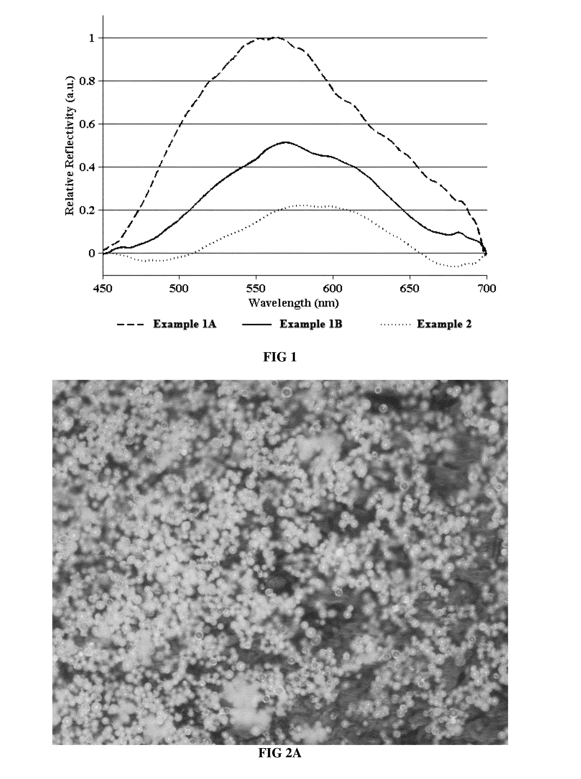
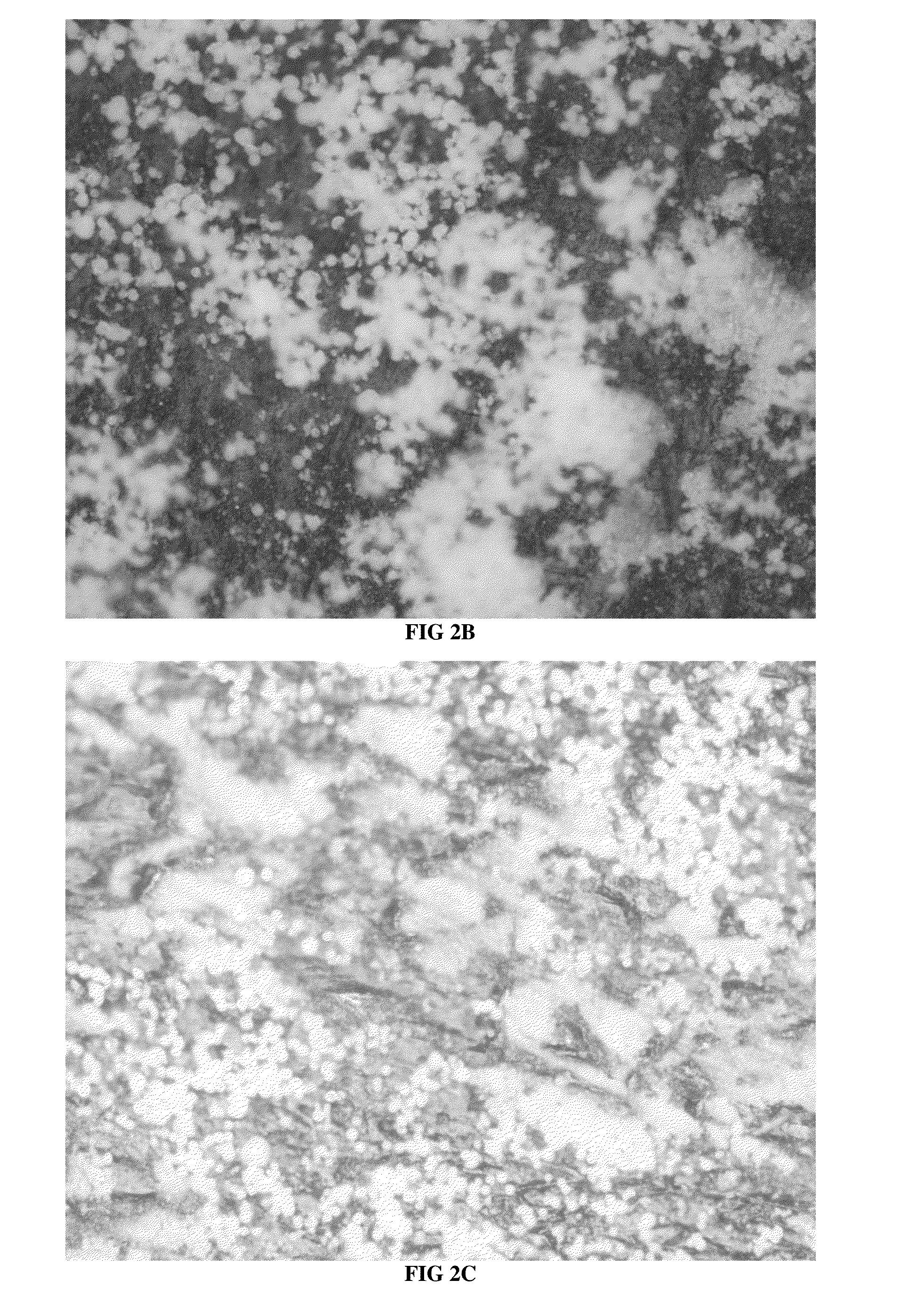
[0082]The following photonic crystal microspheres shown in Table 1 are each assembled by the mono-dispersed particles and the co-assembly material. Specifically, the mono-dispersed particles are assembled in a closely-packed and regularly-ordered structure, with interstition therebetween, forming the photonic crystal microsphere. The co-assembly material is contained in the interstition. Table 1 also indicates the color shown by each photonic crystal microsphere.

TABLE 1Mono-dispersed ParticlesParticle sizeMaterialaverageCo-assembly MaterialColor1ACore of Polystyrene215 nm with a PDI ofPolyacrylamideGreen(“PS”) and shell ofbelow 0.05poly(methylmethacrylate-co-acrylic acid)(“PMMA-PAA”)1BCore of PS and shell215 nm with a PDI ofNanocrystalline TiO2Greenof PMMA-PAAbelow 0.05particles with a particlesize of 18-22 nm1CPS284 nm with a PDI ofPolyacrylamideRedbelow 0.051DPS253 nm with a PDI ofNanocrystalline TiO2Orangebelow 0.05particles with a particlesize of 18-...


PUM

PropertyMeasurementUnit
particle sizeaaaaaaaaaa

Abstract

A photonic crystal microsphere, comprising: a plurality of mono-dispersed polymer particles in a closely-packed and regularly-ordered structure, with interstition therebetween, forming the photonic crystal microsphere; and a co-assembly material contained in the interstition. The photonic crystal microsphere provides a structure of enhanced strength and a good color effect.

Description

FIELD OF THE INVENTION[0001]The present invention relates to a photonic crystal microsphere comprising a plurality of mono-dispersed particles and a co-assembly material. The present invention also relates to a method of making the photonic crystal microsphere, and a photonic crystal pigment comprising the photonic crystal microsphere.BACKGROUND OF THE INVENTION[0002]Photonic crystal microspheres built up by mono-dispersed particles have been known to yield color effects as a result of the periodic arrangement of the mono-dispersed particles therein. Specifically, a plurality of mono-dispersed particles is assembled in a closely-packed and regularly-ordered structure to form one photonic crystal microsphere. This highly organized structure, with the size of the mono-dispersed particles in the range of wavelength of visible light, selectively diffracts certain wavelengths and therefore renders a color corresponding to the diffracted wavelengths. The color effects can be optimized by ...

Claims


Application Information

Patent Timeline
Patent Type & Authority Applications(United States)
IPC IPC(8): G02B1/00G02B1/04
CPCG02B1/04G02B1/005C08F2/22C08F220/56C08F222/385C30B5/00C30B29/16C30B29/46C30B29/58C30B29/60C08F212/08C08F220/14C08F220/06
Inventor LI, MINGZHUYANG, QIANGSONG, YANLINWANG, LIBINYANG, LIANGWANG, PING
Owner THE PROCTER & GAMBLE COMPANY
Why Eureka
Try Eureka