Biaxial optical deflector including multiple mirror units, radar system and its manufacturing method

a technology of optical deflector and mirror unit, which is applied in the direction of reradiation, distance measurement, instruments, etc., can solve the problems of low operation speed of th, inability to operate the mems mirror at a high scanning speed, and limited angular view and angular resolution

Active Publication Date: 2016-06-16
STANLEY ELECTRIC CO LTD
View PDF1 Cites 19 Cited by
  • Summary
  • Abstract
  • Description
  • Claims
  • Application Information

AI Technical Summary

Benefits of technology

[0016]According to the presently disclosed subject matter, since a biaxial deflector is constructed by multiple mirror units, each of the mirror units can be operated for high speed scanning so that areas irradiated by the mirror units can be continuous, thus realizing a single large mirror.

Problems solved by technology

However, the larger the size of the MEMS mirror, the lower the operation speed of the
Note that since the resonant frequency of the MEMS mirror for a wider angular scanning is about several hundreds of Hz, it is impossible to operate the MEMS mirror at a high scanning speed.
In the above-described prior art laser radar system, however, when the number of laser light sources is smaller, the angular view and angular resolution are limited.
On the contrary, when the number of laser light sources is larger, the manufacturing cost would be increased.
Also, it is difficult to continuously scan the irradiation angle of laser beam over the laser light sources, so that irradiation areas or areas scanned by the laser light sources are discrete, i.e., not continuous.

Method used


Image

  • Biaxial optical deflector including multiple mirror units, radar system and its manufacturing method
  • Biaxial optical deflector including multiple mirror units, radar system and its manufacturing method
  • Biaxial optical deflector including multiple mirror units, radar system and its manufacturing method

Examples


Embodiment Construction

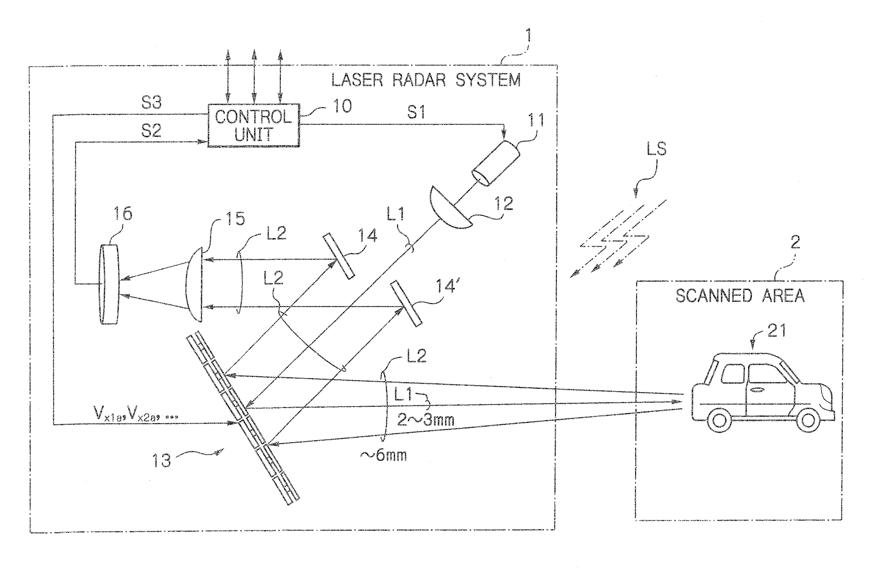
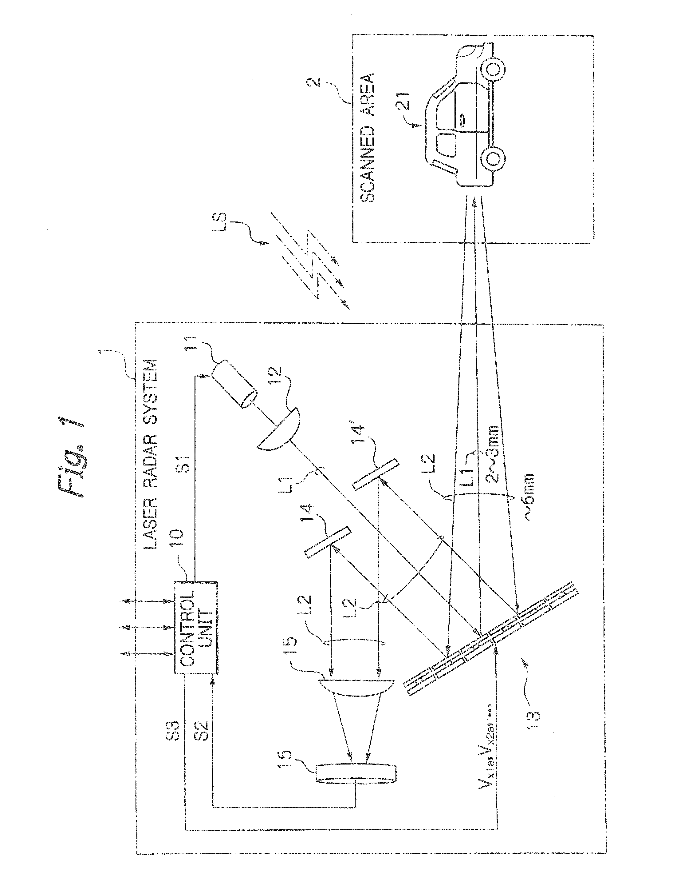
[0031]In FIG. 1, which is a schematic view illustrating an embodiment of the laser radar system according to the presently disclosed subject matter, a laser radar system 1, that may be mounted on a driver's vehicle, monitors an object such as a preceding vehicle 21 in a scanned area 2 to detect a distance and angle between the driver's vehicle and the preceding vehicle 21. For example, the distance between the driver's vehicle and the preceding vehicle 21 may be 100 m.

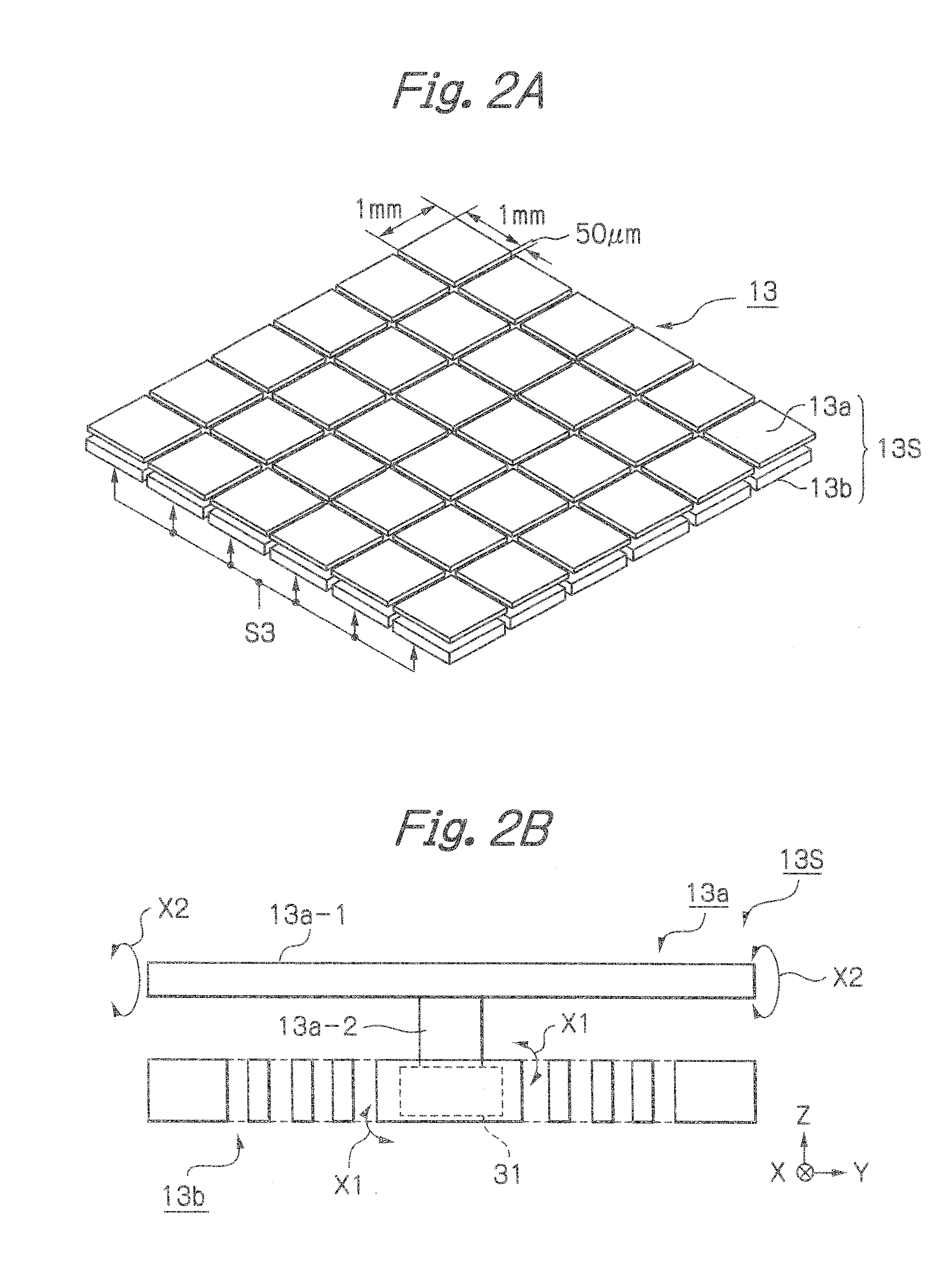
[0032]The laser radar system 1 is constructed by a control unit 10 such as a microcomputer, a single laser light source 11, a projection lens 12, a biaxial optical deflector (mirror array) 13, two or more fixed mirrors 14 and 14′, a light convergence lens 15 and a photo detector 16.

[0033]The laser light source 11 is driven by a signal S1 from the control unit 10 to emit an about 2 to 3 mm beam-diameter collimated laser beam L1 which passes through the projection lens 12 to the biaxial optical deflector 13. Note that th...


PUM


Abstract

In a biaxial optical deflector, multiple mirror units are arranged in an array. Each of the mirror units includes one mirror and one mirror driver coupled to said mirror for rocking the mirror.

Description

[0001]This application claims the priority benefit under 35 U.S.C. §119 to Japanese Patent Application No. JP2014-249824 filed on Dec. 10, 2014, which disclosure is hereby incorporated in its entirety by reference.BACKGROUND[0002]1. Field[0003]The presently disclosed subject matter relates to a biaxial optical deflector, a radar system using the same and its manufacturing method.[0004]2. Description of the Related Art[0005]In an automobile safety system, a laser radar system is provided to detect a distance and angle between the driver's vehicle and its object or preceding vehicle. As a result, when the distance between the driver's vehicle and its preceding vehicle is smaller, the driver's vehicle is automatically decelerated for a time or a distance and, at worst, the driver's vehicle is stopped.[0006]Such a laser radar system requires a function for scanning an object or a preceding vehicle at a wide angular view with a high angular resolution to avoid a dead space. Particularly,...

Claims


Application Information

Patent Timeline
Patent Type & Authority Applications(United States)
IPC IPC(8): G02B26/08G02B26/12G01S7/481G01S17/931
CPCG02B26/0858G02B26/12G01S7/4817G02B26/123G01S17/931
Inventor YASUDA, YOSHIAKI
Owner STANLEY ELECTRIC CO LTD
Why Eureka
Try Eureka