Phase shifter, phased-array antenna, and radar

a phase shifter and antenna technology, applied in waveguides, instruments, antennas, etc., can solve the problems of difficult to move the dielectric plate back and forth at high speed, difficult to maintain high mechanical reliability, and no example in which a typical phase shifter is applied to a transmission lin

Inactive Publication Date: 2004-05-18
MURATA MFG CO LTD
View PDF9 Cites 13 Cited by
  • Summary
  • Abstract
  • Description
  • Claims
  • Application Information

AI Technical Summary

Benefits of technology

To this end, the present invention provides a phase shifter including a substantially planar dielectric plate, a conductive strip formed on the dielectric plate, and a rotator at least partially including a conductor and a dielectric, the rotator being positioned in proximity to the conductive strip so as to freely rotate.
In another aspect of the present invention, a radar includes any of the above-described phased-array antennas, and a transceiver using the phased-array antenna for transmission and reception. The radar can thus perform high-speed scanning and can be highly shock-resistant. In addition, a simple motor can be used to perform the phase control at high speed and to maintain sufficiently high mechanical reliability.

Problems solved by technology

However, such typical phase shifters or phased-array antennas have the following problems.
The structure which facilitates the back-and-forth movement of the dielectric plate makes it difficult to maintain high mechanical reliability, and also makes it difficult to move the dielectric plate back and forth at high speed.
Furthermore, there has been no example in which a typical phase shifter is applied to a transmission line, such as a microstrip line, formed on a dielectric plate or a dielectric line formed by placing a dielectric strip between two metal plates.
A typical phased-array antenna requires a removable spacer plate to be moved back and forth in order to control feed phase with respect to a plurality of slot antennas, and it is difficult to control the phase at high speed.

Method used


Image

  • Phase shifter, phased-array antenna, and radar
  • Phase shifter, phased-array antenna, and radar
  • Phase shifter, phased-array antenna, and radar

Examples


third embodiment

A phased-array antenna according to the present invention is now described with reference to FIG. 7.

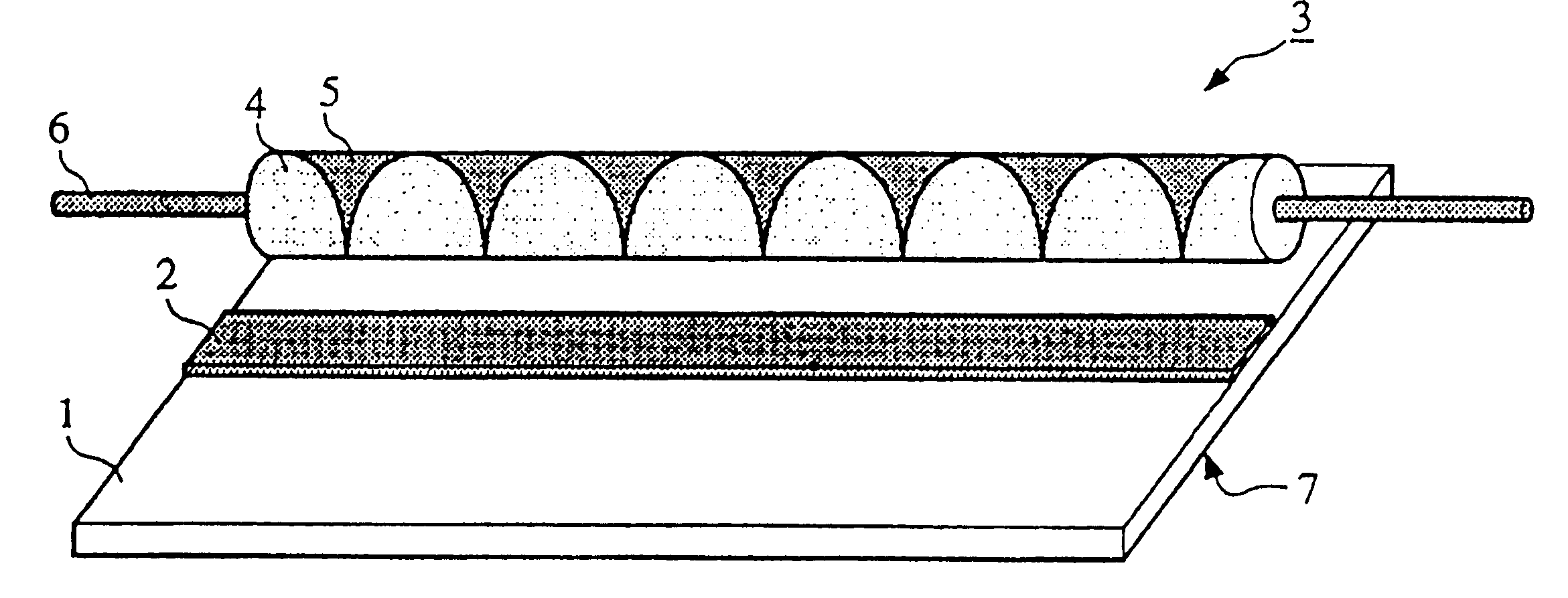
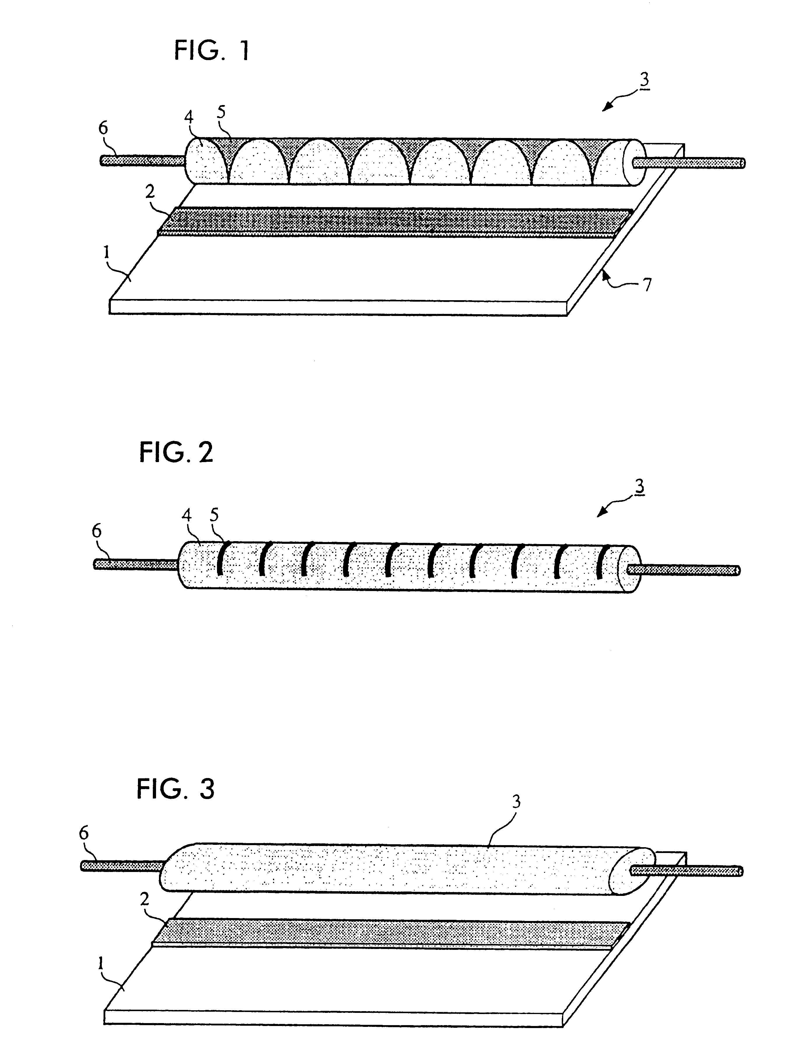
In FIG. 7, a conductive strip (strip line) 2 is formed on the top surface of a dielectric plate 1. A ground electrode is formed on substantially the entirety of the under surface of the dielectric plate 1, in which a plurality of slots 8 are formed so that the electrode is partially made open at predetermined positions.

The dielectric plate 1, the ground electrode on the under surface, and the conductive strip 2 form a microstrip line, from which an electromagnetic field radiates downward through the slots 8. If a feed is in-phase with respect to the slots 8, the axis of the beam is directed orthogonally to the dielectric plate 1. If a feed is out-of-phase with respect to the slots 8, so that the phase is progressively delayed or advanced along the conductive strip 2, beam scanning can be performed on the plane orthogonal to the dielectric plate 1. As previously described with referenc...

fourth embodiment

A phased-array antenna according to the present invention is now described with reference to FIG. 8.

In FIG. 8, a conductive strip 2 and microstrip antenna patches 9 are formed on the top and under surfaces of a dielectric plate 1, respectively. The patches 9 on the under surface of the dielectric plate 1 are coupled with the conductive strip 2 on the top surface. The line formed by the conductive strip 2 serves as a feed line for the microstrip antennas. As the gap between the conductive strip 2 and the rotator 3 changes, the feed shifts the phase with respect to the microstrip antennas. This results in beam scanning in the same way as shown in FIG. 7.

fifth embodiment

A phased-array antenna according to the present invention is now described with reference to FIG. 9.

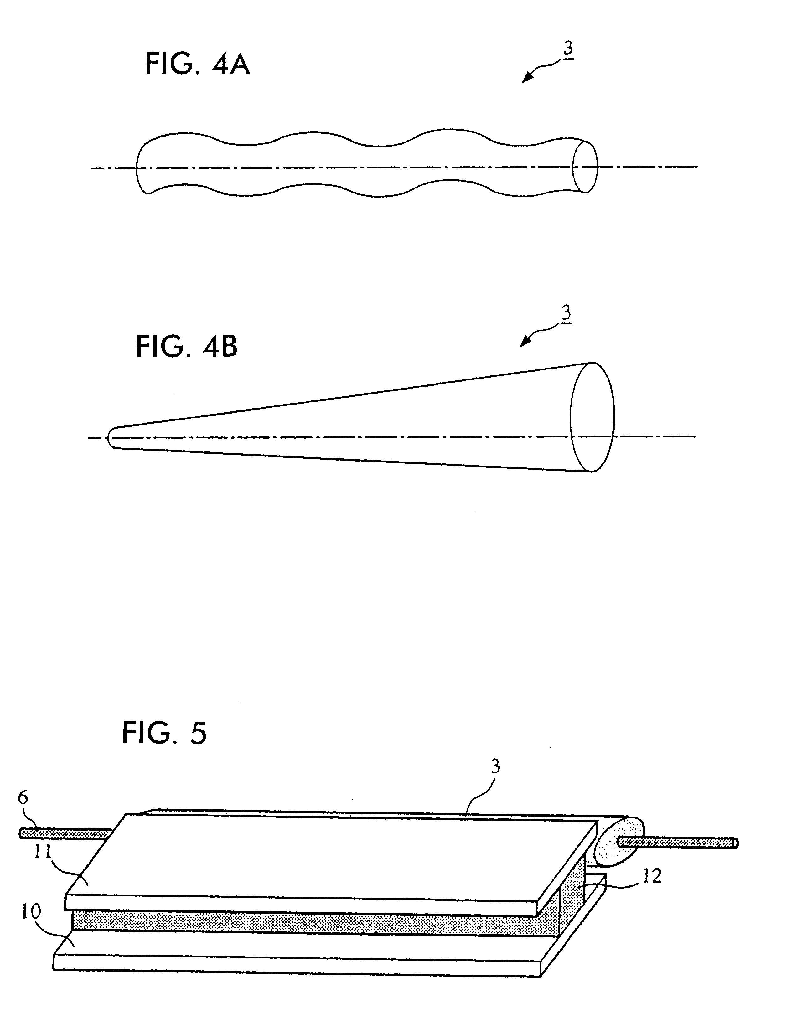
In FIG. 9, a dielectric strip 12 is placed between conductive plates 10 and 11, thereby forming a dielectric line. As shown in FIG. 9, a plurality of slots 8 are formed in the conductive plate 10. Electromagnetic waves propagating on the dielectric line are emitted through the slots 8, serving as slot antennas. A rotator 3 which is constructed in the same manner as previously described for the phase shifter is positioned at one side of the dielectric strip 12, and the phase constant of the dielectric strip 12 changes as the rotator 3 rotates. However, the shape of the rotator 3 is determined so that the phase constant progressively changes in the direction of electromagnetic propagation on the dielectric line. Therefore, the feed progressively shifts in phase with respect to the slots 8 in the direction of electromagnetic propagation on the dielectric line as the rotator 3 rotates, re...


PUM


Abstract

A phase shifter includes upper and lower conductive plates, and a dielectric strip sandwiched between the conductive plates, and a plurality of slots formed in the upper conductive plate, thereby forming a dielectric line. A rotator is positioned at either side of the dielectric strip so that the distance from the rotator to the dielectric strip varies as the rotator rotates. As the rotator rotates, the phase constant of the dielectric line progressively changes in the direction of electromagnetic propagation. The rotation of the rotator causes a change in feed phase with respect to the slots as the rotator rotates, thereby performing beam scanning.

Description

1. Field of the InventionThe present invention relates to a phase shifter for shifting the phase of signals propagating on a transmission line, and to a phased-array antenna and radar incorporating the phase shifter.2. Description of the Related ArtA typical phase shifter for shifting the phase of electromagnetic waves propagating on a transmission line includes a dielectric plate which is positioned with respect to a waveguide so as to be freely insertable into the waveguide.In an exemplary phased-array antenna including arrays of a plurality of slot antennas, a movable spacer plate can be moved back and forth to control feed phase with respect to each of the slot antennas to perform beam scanning.However, such typical phase shifters or phased-array antennas have the following problems.Since a typical phase shifter controls the phase by adjusting the amount by which the dielectric plate is inserted into the waveguide, for example, it is necessary to move the dielectric plate back a...

Claims


Application Information

Patent Timeline
Patent Type & Authority Patents(United States)
IPC IPC(8): H01Q3/30H01Q3/32H01Q3/26H01P1/18G01S7/02H01Q13/20H01Q21/06
CPCH01Q3/26H01Q3/32
Inventor KITAMORI, NOBUMASAHIRATSUKA, TOSHIRO
Owner MURATA MFG CO LTD
Why Eureka
Try Eureka