Optical stimulation apparatus and optical-scanning examination apparatus

a technology of optical stimulation and examination apparatus, which is applied in the direction of optical radiation measurement, fluorescence/phosphorescence, instruments, etc., can solve the problems of high cost, increased overall size of the apparatus, and difficulty in scanning at a speed higher than

Inactive Publication Date: 2005-11-17
OLYMPUS CORP
View PDF15 Cites 13 Cited by
  • Summary
  • Abstract
  • Description
  • Claims
  • Application Information

AI Technical Summary

Benefits of technology

[0010] In light of the drawbacks described above, it is an object of the present invention to provide an optical stimulation apparatus and an optical-scanning examination apparatus in which a position where an optical stimulus is applied to a specimen can be scanned at high speed and in which the optical stimulus position can be fixed at a specific position.

Problems solved by technology

However, the oscillation frequency of galvano mirrors is generally about 500 Hz, and therefore, it is difficult to scan at a speed higher than this.
Also, detectors for detecting the angle of the galvano mirrors must be provided, which tends to increase the overall size of the apparatus.
In addition, increasing the oscillation frequency reduces the light intensity, and hence it is necessary to provide a high-sensitivity detector, which results in the problem of higher costs.
Increasing the intensity of the illumination light to compensate for the detector sensitivity, may result in damage to the specimen, which is undesirable.
Furthermore, galvano mirrors that oscillate at high speed, such as resonant galvano mirrors, are also available; however, since the detector sensitivity is limited, they are not effective for use in acquiring images, and they also suffer from the drawback that the light beam cannot be stopped at a specific position.

Method used


Image

  • Optical stimulation apparatus and optical-scanning examination apparatus
  • Optical stimulation apparatus and optical-scanning examination apparatus
  • Optical stimulation apparatus and optical-scanning examination apparatus

Examples


Embodiment Construction

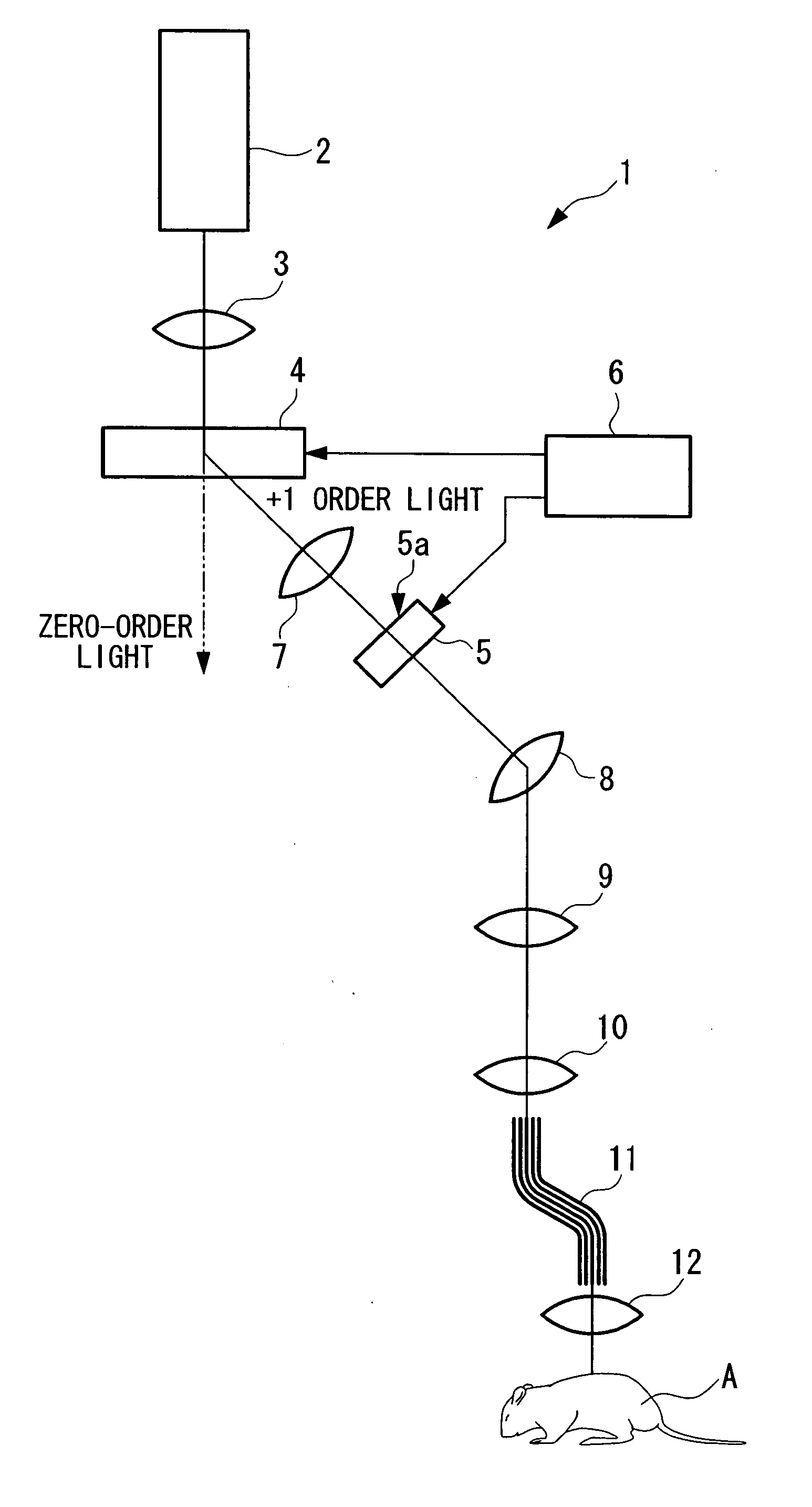
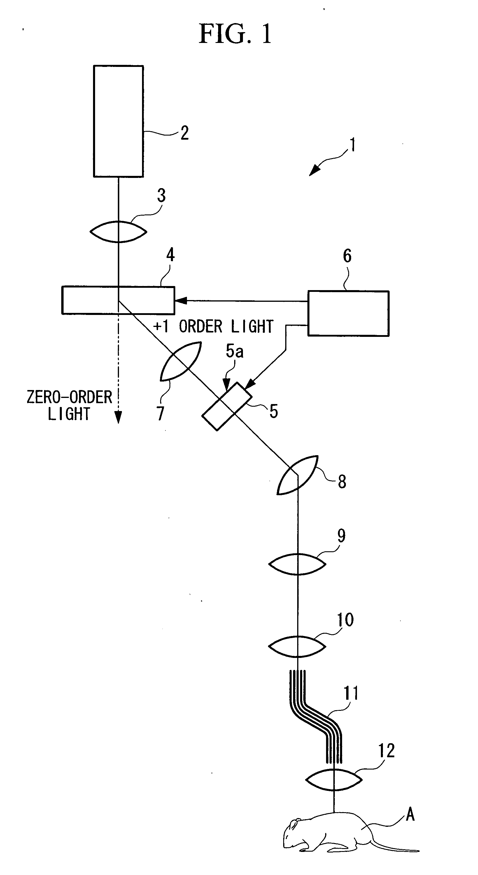
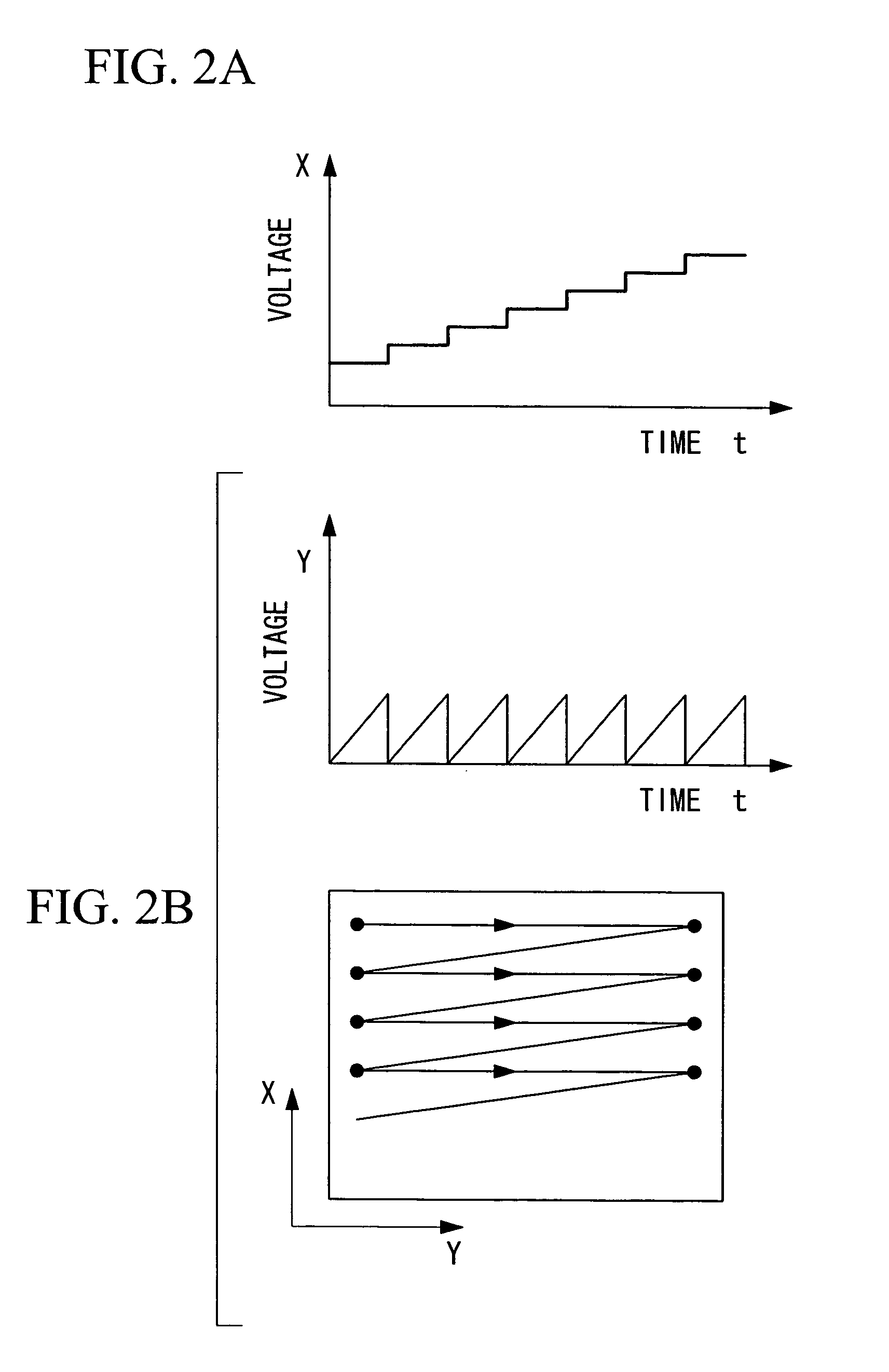
[0028] An optical stimulation apparatus according to a first embodiment of the present invention is described below with reference to FIG. 1 and FIGS. 2A to 2C.

[0029] As shown in FIG. 1, the optical stimulation apparatus 1 of this embodiment includes a laser light source 2 that emits laser light; a beam expander 3 that expands the laser beam; a first acousto-optic device (AOD) 4; a second acousto-optic device 5; an AOD control apparatus 6 that controls the acousto-optic devices 4 and 5; a telescope lens 7 that maintains the beam emitted from the first acousto-optic device 4 at a specific beam diameter; a pupil-projection lens 8 that forms an intermediate image of the light emitted from the second acousto-optic device 5; an imaging lens 9 that focuses the light forming the intermediate image by the pupil-projection lens 8; a first objective lens 10 that images the light focused by the imaging lens 9; an optical fiber bundle 11 of which one end is disposed at the image position of th...


PUM

PropertyMeasurementUnit
oscillation frequencyaaaaaaaaaa
frequencyaaaaaaaaaa
opticalaaaaaaaaaa

Abstract

The invention provides an optical stimulation apparatus including a light source; a scanning unit that scans light from the light source; and an objective optical system that images the light scanned by the scanning unit onto a specimen. The scanning unit includes an acousto-optic device that varies the diffraction angle in response to a vibration frequency input thereto.

Description

BACKGROUND OF THE INVENTION [0001] 1. Field of the Invention [0002] The present invention relates to an optical stimulation apparatus and to an optical-scanning examination apparatus. [0003] 2. Description of Related Art [0004] Conventionally, as an optical microscope in which a specimen such as a living organism can be subjected to magnified in-vivo examination, the optical fiber microscope disclosed in Japanese Unexamined Patent Application Publication No. 2003-344777 (FIG. 1 therein) has been suggested. This microscope includes a first objective lens that images laser light emitted from a laser light source onto one end of an optical fiber bundle, and a second objective lens disposed at the other end of the optical fiber bundle, and is configured such that the laser light from the laser light source is two-dimensionally scanned on the specimen with a laser-light scanner. [0005] Examples of the laser-light scanner include galvano mirrors and polygon mirrors which vary the reflecti...

Claims


Application Information

Patent Timeline
Patent Type & Authority Applications(United States)
IPC IPC(8): G02B21/06G01J3/44G01N21/64G02B21/00G02B21/16H01J5/16
CPCG01J3/0208G01J3/0229G01J3/0235G01J3/4406G01N21/6456G02B21/0044G02B21/002G02B21/0032G02B21/0036G02B21/16G01N2021/6463
Inventor NAKATA, TATSUO
Owner OLYMPUS CORP
Why Eureka
Try Eureka