Smart Multicoil Inductively-Coupled Array for Wireless Power Transmission

Active Publication Date: 2016-06-16
POLYVALOR LP +1
View PDF0 Cites 16 Cited by
  • Summary
  • Abstract
  • Description
  • Claims
  • Application Information

AI Technical Summary

Benefits of technology

[0009]The proposed approach 1) can deliver power with superior efficiency over longer separation distances without the need for a closed loop power management unit, 2) can naturally track the receiver position and localize transmitted power through nearby coil array elements without the ne

Problems solved by technology

Thus, each coil of the array is tuned to a different resonance frequency, which is challenging to implement and yields limit

Method used


Image

  • Smart Multicoil Inductively-Coupled Array for Wireless Power Transmission
  • Smart Multicoil Inductively-Coupled Array for Wireless Power Transmission
  • Smart Multicoil Inductively-Coupled Array for Wireless Power Transmission

Examples


examples

[0088]In a 3-coil example configuration, at a carrier frequency of 200 kHz, the chamber prototype presents a PTE of 83.3% and a PDL of 3.87 W, which is perfectly suitable for short range applications. In a 4-coil example configuration, at 13.56 MHz, the proposed chamber prototype presents a PTE of 76% and 53% for separation distances of 4 cm and 8 cm, respectively. Moreover, the chamber prototype can achieve high PDL of 115 mW and 80 mW across separation distances of 4 cm and 8 cm, respectively.

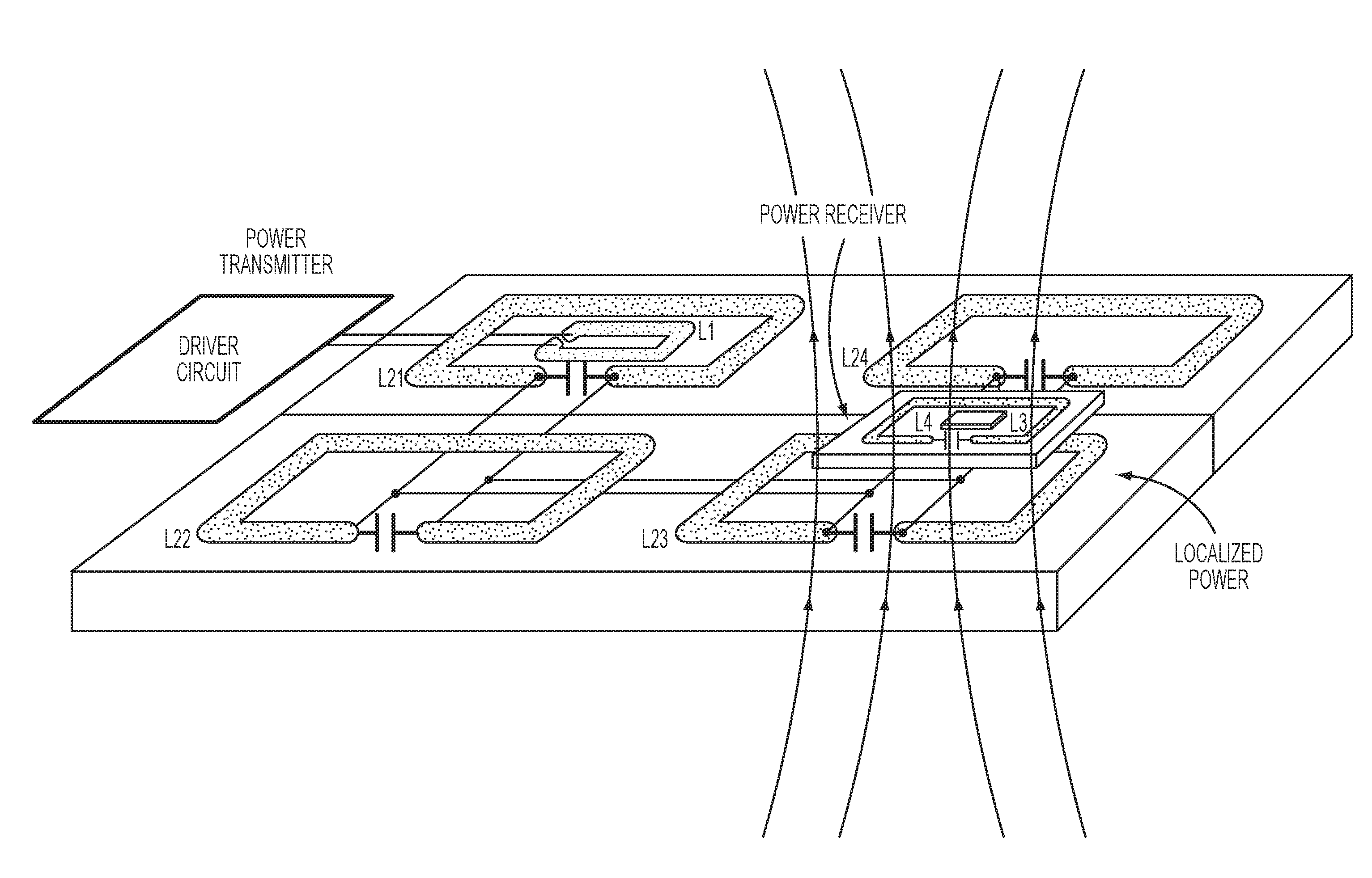
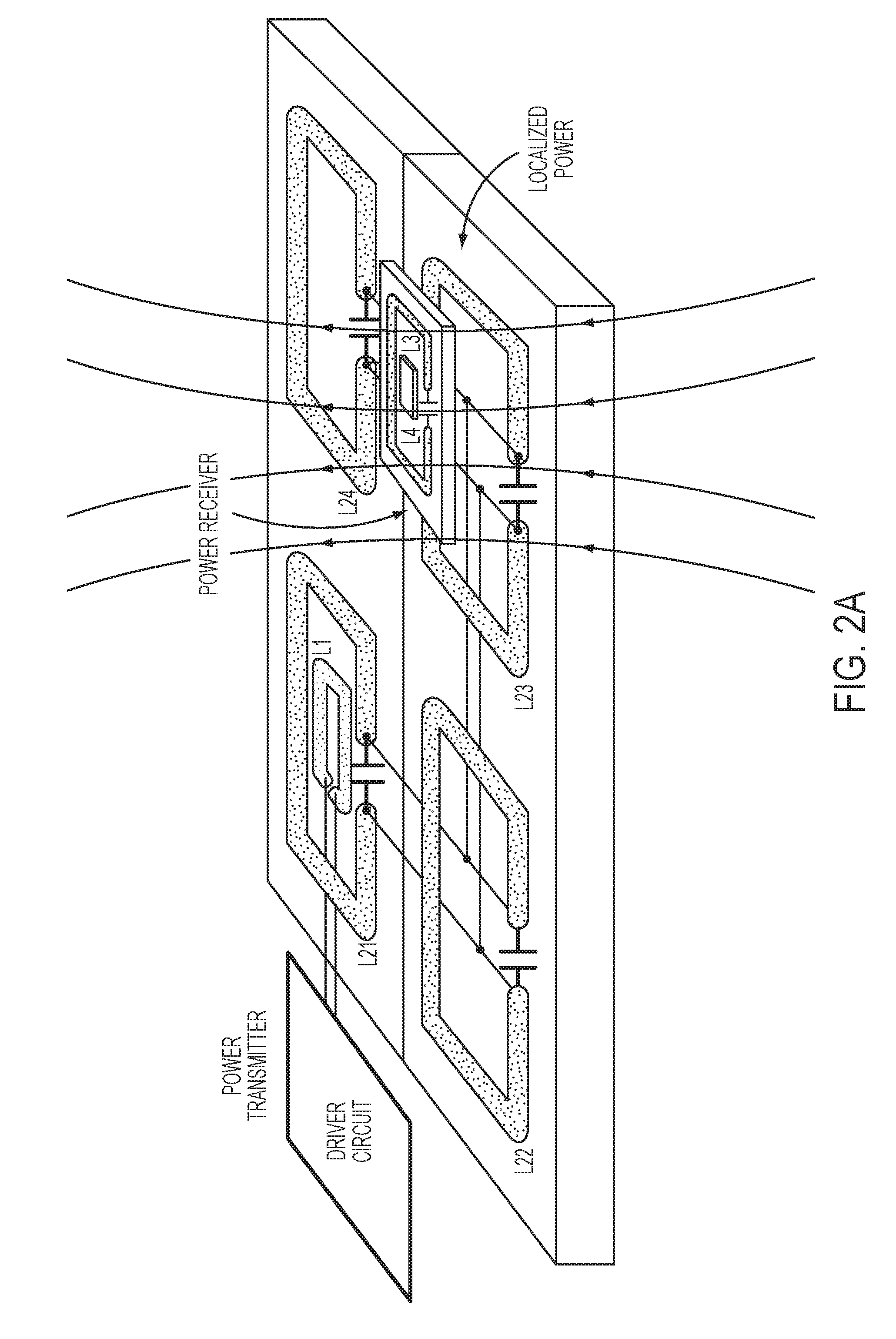
[0089]Another example of a comparison between a prior art system and the invention is described in relation with FIG. 16. A wireless mobile unit in the form of a portable device or electrical vehicle with receiver (Rx) coil is inductively powered by an array of transmitter coils that cover a surface, such as a table, a road or a car parking. A chain of transmitter resonators can be employed for providing the electromagnetic field for a larger area than the optimized single transmitter resonat...


PUM


Abstract

A power surface or chamber having nearly constant electromagnetic field distribution in 3D comprising at least one primary coil and one primary resonance array made of several coils connected in parallel for generating the electromagnetic field distribution; a single power driver circuit for activating the coils; and a secondary coil and an optional secondary resonance coil to recover the generated electromagnetic field and power up an electric device.

Description

TECHNICAL FIELD[0001]The invention relates to wireless power transmission and more particularly to a multicoil inductively-coupled array.BACKGROUND OF THE ART[0002]Nowadays power transmission systems based on inductive coupling are becoming increasingly popular to charge a wide variety of battery powered devices, ranging from handheld electronics, such as cell phones, tablets and computer mouses, to electric vehicles. Key characteristics for such systems are ease of use, high energy transfer efficiency, short charging time and low-cost.[0003]On the other hand, there are several applications in which an electronic device cannot use batteries as a primary source of energy. Implantable devices and smart animal research systems are examples of such applications. In these systems, power is delivered wirelessly in air or across the skin through an inductive link formed by mutually coupled coils to limit risks of infection and any dangerous tethering associated with transcutaneous wires.[0...

Claims


Application Information

Patent Timeline
IPC IPC(8): H01F38/14H02J5/00H02J7/02
CPCH01F38/14H02J5/005H02J7/025H02J50/12H02J50/402
Inventor MIRBOZORGI, SEYEDABDOLLAHGOSSELIN, BENOITSAWAN, MOHAMAD
Owner POLYVALOR LP
Why Eureka
Try Eureka