Method for producing a tube of glass

a technology of glass tubes and glass tubes, applied in glass tempering apparatuses, manufacturing tools, other domestic objects, etc., can solve the problems of increasing the end diameter of the tube, affecting the quality of glass tubes, and affecting the quality of glass tubes, and achieve the effect of high dimensional stability

Active Publication Date: 2016-06-23
HERAEUS QUARZGLAS
View PDF1 Cites 4 Cited by
  • Summary
  • Abstract
  • Description
  • Claims
  • Application Information

AI Technical Summary

Benefits of technology

[0011]It is an objective of the present invention to provide a method which makes it possible to form a hollow cylinder in a single forming step or in a number of forming steps, which number is as small as possible, into a glass tube with a large outer diameter and high dimensional stability.

Problems solved by technology

Variations in the radial cross-sectional profile or wall one-sidedness; i.e. radially irregular profiles of the tube wall thickness, also called “siding” among the experts, are here particularly disadvantageously noticed.
These problems increase with an increasing end diameter of the tube, for wall thickness variations found in the start cylinder exponentially grow with the diameter in the forming process.
This effect also depends on the level of the blow pressure, so that this pressure cannot be arbitrarily high.
This, in turn, leads to more drawing streaks or other defects in the glass wall and to an increased energy demand, especially in the case of large-volume tubes (also called “large tubes” hereinafter) which cool down very rapidly because of their large volume.
The greater the end diameter of the tube, the more difficult and more cost-intensive is therefore the production of a dimensionally stable large tube.
On the other hand, it is evident that this procedure requires a lot of time and energy, especially since the tube cools down between successive forming steps.
It has, however, been found that the forming process in the case of very great diameter changes becomes unstable, which first manifests itself in diameter variations that form a wave structure extending in the longitudinal axis direction.

Method used


Image

  • Method for producing a tube of glass
  • Method for producing a tube of glass
  • Method for producing a tube of glass

Examples


example

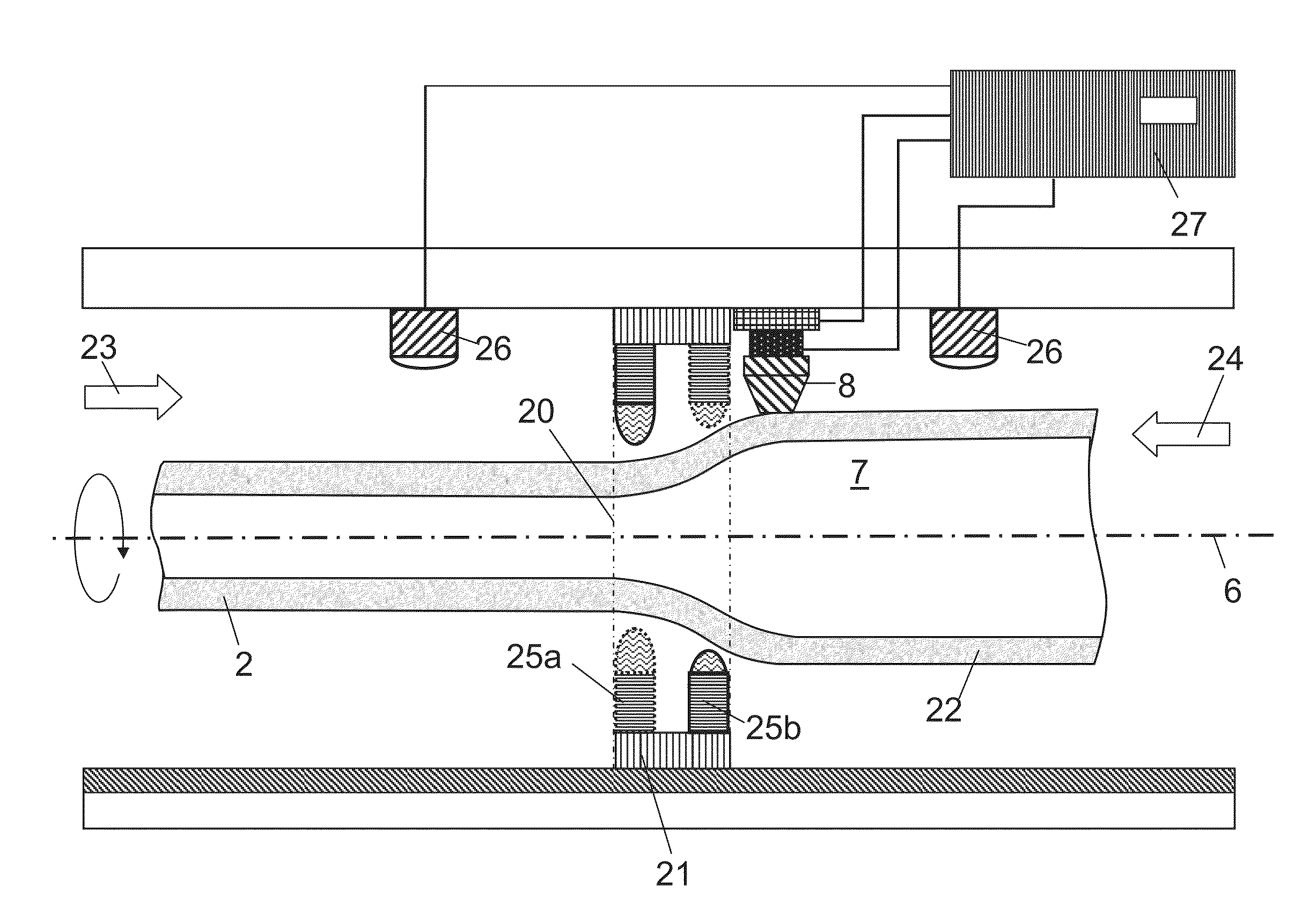
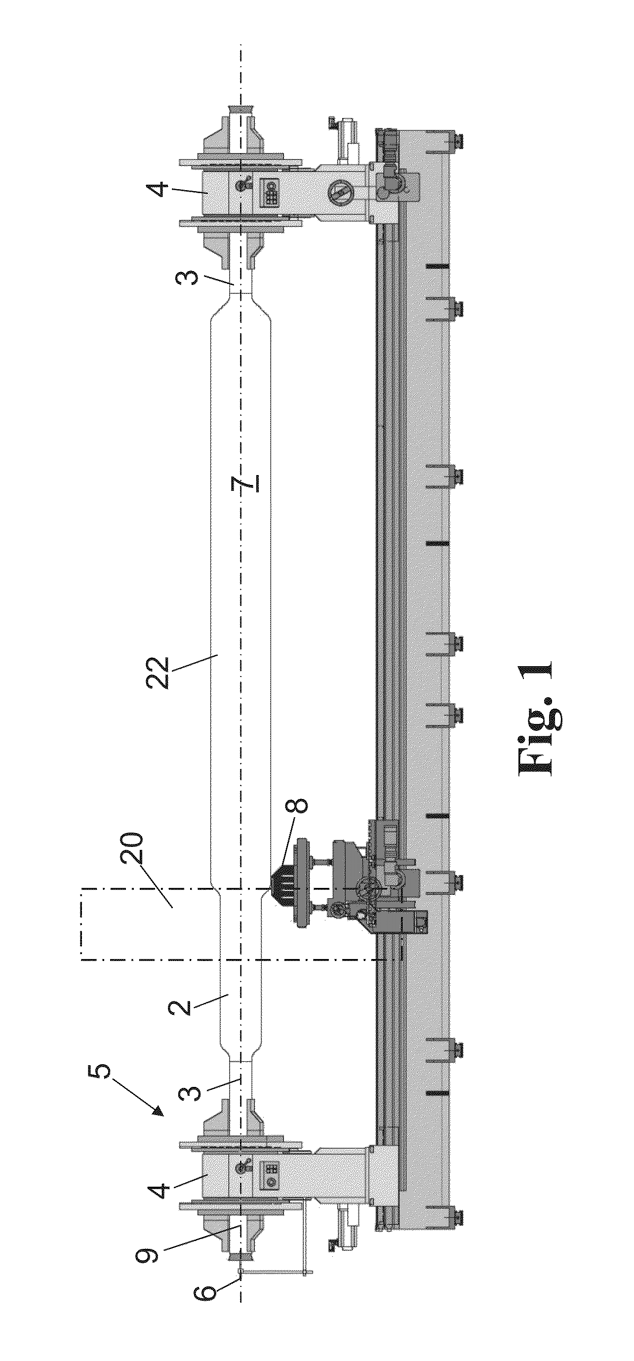
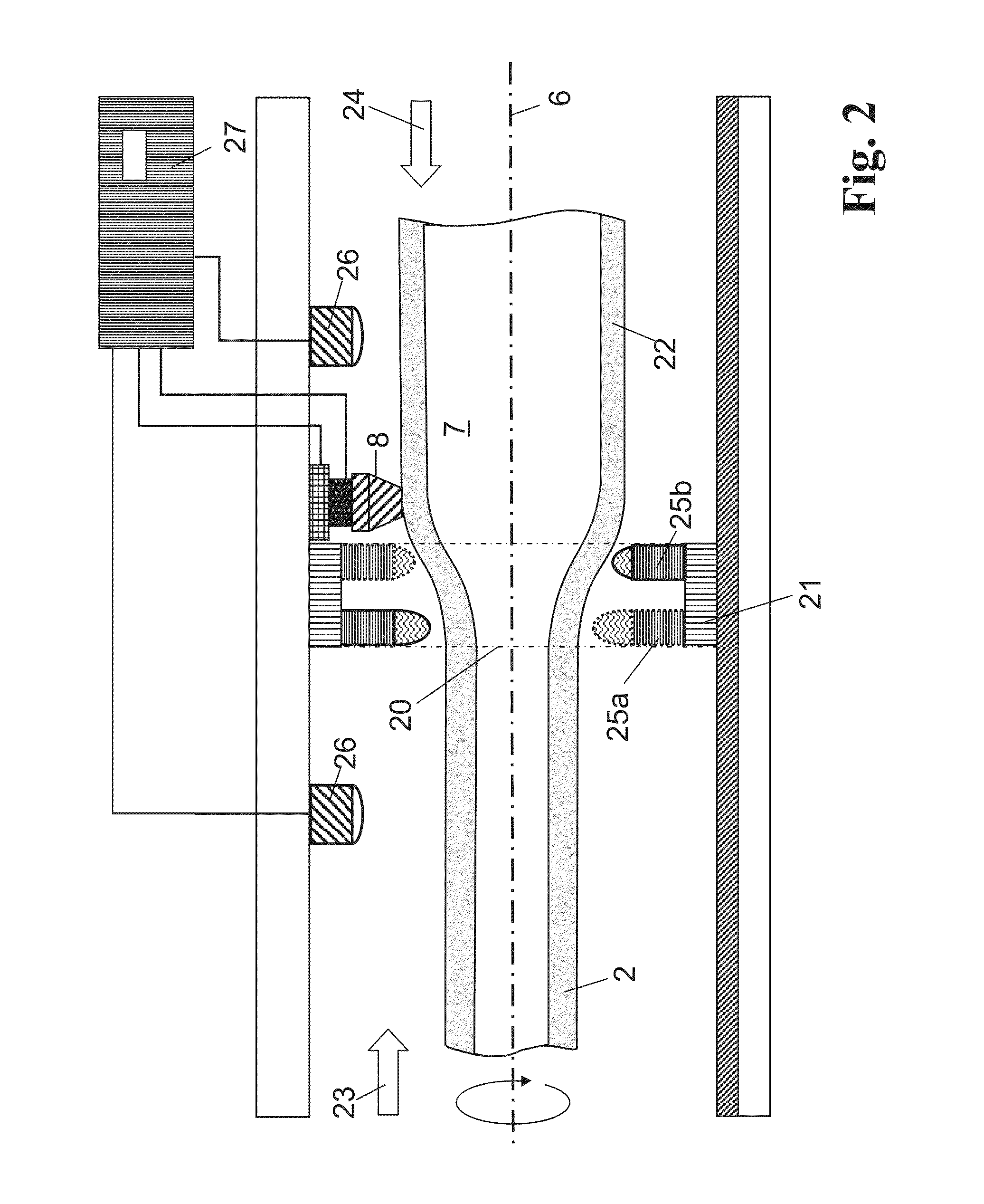
[0057]Due to the advance movement of the burner carriage 21 at a speed of 4 cm / min, the hollow cylinder 2, while rotating about its longitudinal axis 6 (which corresponds to the rotation axis) at a speed of 60 rpm, is heated continuously under the action of the burner rings 25a, 25b to a high temperature of around 2,100° C. In the rear burner ring 25b, a smaller heating output is generated than in the front burner ring 25a, resulting in a total heating output density that will be explained in more detail further below with reference to FIG. 5. To achieve a radial expansion rate that is as constant as possible along the deformation zone, the axial profile of the heating output curve is here decisive (not so much the absolute value).

[0058]The inner bore 7 can here be flushed with a gas, and a defined and controlled internal pressure of up to about 100 mbar is here set in the inner bore 7. In the embodiment, a blow pressure of 15 mbar is applied.

[0059]The quartz glass is given such a l...


PUM

PropertyMeasurementUnit
blow pressureaaaaaaaaaa
outer diameter D1aaaaaaaaaa

Abstract

A method for forming a hollow cylinder, in a single step or in as small a number of steps as possible, into a quartz glass tube with a large outer diameter and high dimensional stability is provided. The cylinder, while rotating about a rotation axis, is softened in portions in a heating zone which is moved at a relative feed rate Va, and the softened portion is radially expanded by a centrifugal force and/or an internal overpressure applied in the hollow cylinder bore so as to form a deformation zone. The tube is continuously shaped with an outer diameter D2 which is greater than that of the hollow cylinder D1. The radial expansion of the softened portion is carried out at a location-dependent radial expansion rate Vr, the profile of which along the deformation zone has a maximum value Vr,max which is smaller than two times the feed rate Va.

Description

BACKGROUND OF THE INVENTION[0001]The present invention relates to a method for producing a tube of glass, particularly of quartz glass, by forming a hollow cylinder from the glass with an outer diameter D1 in that the cylinder, while rotating about a rotation axis, is softened in portions in a heating zone which is moved at a relative feed rate Va, and the softened portion is radially expanded under the action of a centrifugal force and / or of an internal overpressure applied in the hollow cylinder bore so as to form a deformation zone, and the tube is continuously shaped with an outer diameter D2 which is greater than D1.[0002]With such methods and apparatuses, hollow cylinders of glass, particularly of quartz glass, are formed in one or plural hot forming steps into tubes, the radial tube dimensions being changed with respect to the radial dimensions of the hollow cylinder or the cross-sectional profile. An initial hollow cylinder which is rotating about its longitudinal axis is he...

Claims


Application Information

Patent Timeline
Patent Type & Authority Applications(United States)
IPC IPC(8): C03B23/053C03B23/08C03B23/07
CPCC03B23/053C03B23/08C03B23/07B23K26/38B23K26/53B23K2103/54B23K2101/06
Inventor GROMANN, BORISWHIPPEY, NIGEL
Owner HERAEUS QUARZGLAS
Why Eureka
Try Eureka