Hydrocarbon Conversion to Ethylene
a technology of hydrocarbon conversion and ethylene, which is applied in the direction of process and machine control, thermal non-catalytic cracking, instruments, etc., can solve the problems of increased reactor pressure drop, substantial loss of heat transfer, and difficult production of by-products, so as to increase the overall equilibrium production of ethylene, reduce overall energy consumption, and high quantities of ethylene
- Summary
- Abstract
- Description
- Claims
- Application Information
AI Technical Summary
Benefits of technology
Problems solved by technology
Method used
Image
Examples
example 1
[0115]The pyrolysis reaction of this invention can carried out in any reactor capable of temperature, pressure and contact time constraints for producing high quantities of ethylene from hydrocarbon in the pyrolysis feed. In an embodiment, the pyrolysis reactor is a regenerative reactor system such as a regenerative, reverse-flow reactor system.
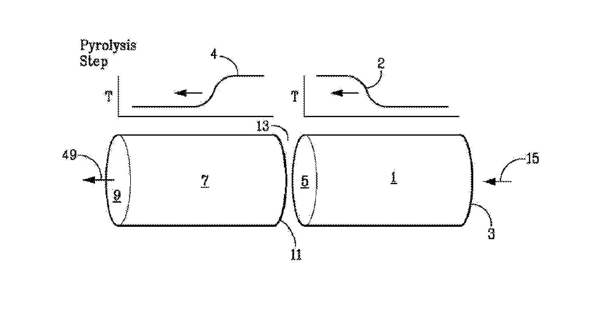
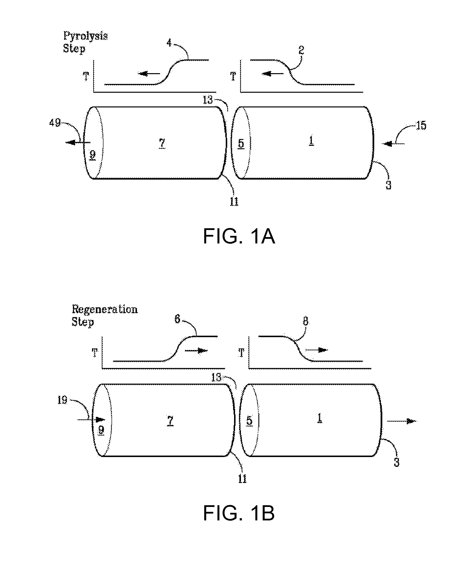
[0116]A basic two-step asymmetric cycle of a regenerative bed reactor system is depicted in FIGS. 1A and 1B. The regenerative bed reactor system is shown as a reactor system having separate thermal mass zones, including a second zone (7) [which includes a recuperator / quenching zone toward a first end (9), as well as a portion of a reaction or pyrolysis zone proximate to a second end (11) of the second zone (7)] and a first zone (1) [also including a portion of the reaction or pyrolysis zone proximate to secondary end (5) of the first zone (1)]. Both the first zone (1) and the second zone (7) contain regenerative beds comprising thermal mass. ...
example 2
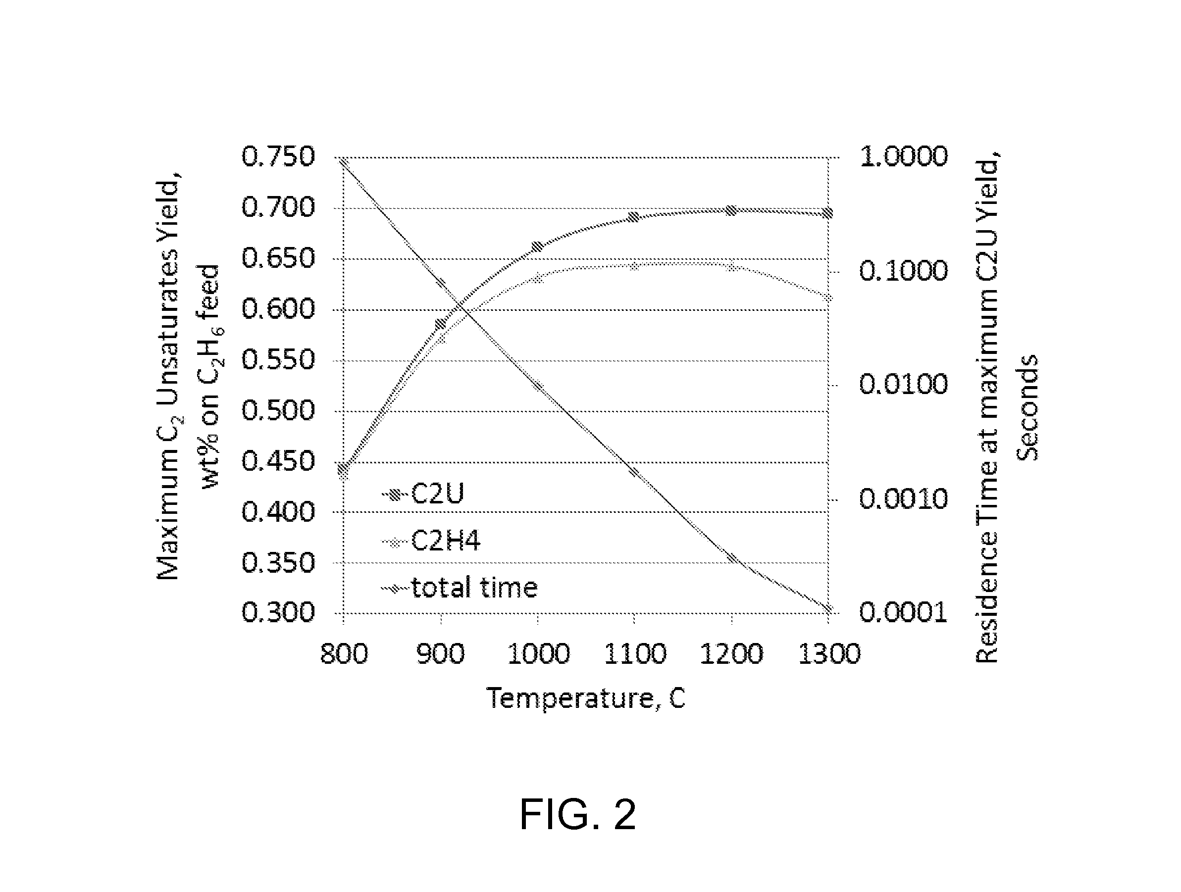
[0121]The impact of temperature and residence time at pyrolysis temperature on C2 unsaturates production is shown in FIG. 2. The data shown in FIG. 2 are based on a model prediction for maximum C2 unsaturates (ethylene+acetylene) yield from hydrocarbon cracking at the indicated cracking temperatures, along with the cracking time needed at the given temperatures. The model used for this Example can be carried out as described by Chen Xu et al., Kinetic Modeling of Ethane Pyrolysis at High Conversion, J. Phys. Chem. A 2011, 115, 10470-10490, which is fully incorporated herein by reference.
[0122]The cases shown in FIG. 2 represent cracking of ethane-containing pyrolysis feed (with the pyrolysis feed comprising 33 mole % steam) at 35 psia (2.4 bara) (initial ethane partial pressure of 23 psia) (1.6 bara). The maximum C2 unsaturates (C2U=ethylene+acetylene) and ethylene (C2H4) yields from the cracking runs are plotted against the cracking temperature.
[0123]FIG. 2 shows that below 900° C....
example 3
[0125]FIG. 3 compares four different predictive runs of pyrolysis processes representative of the invention (Bars B-E) against a conventional steam cracking process (Bar A), with the predictive model being the same as that described in Example 2. All reactions are run at 80% conversion. Total pressure for each run shown in FIG. 3 is as follows: A=21 psig (1.43 barg); B=22 psig (1.5 barg); C=22 psig (1.5 barg); D=60 psig (4.1 barg); E=100 psig (6.8 barg). Partial pressure of the hydrocarbon in each pyrolysis feed stream is shown for each run in FIG. 3. Peak pyrolysis temperature and the total residence time at temperature above 800° C. are also shown in FIG. 3. In runs A, B and E, diluent (water) was included with the pyrolysis feed. Thus, in runs A, B and E, total pressure is equal to the sum of the partial pressures of the hydrocarbon and the water (steam) in the reactor. In cases C and D, no diluent was included with the pyrolysis feed. Thus, in cases C and D, total pressure equal...
PUM
| Property | Measurement | Unit |
|---|---|---|
| temperature | aaaaa | aaaaa |
| residence time | aaaaa | aaaaa |
| residence time | aaaaa | aaaaa |
Abstract
Description
Claims
Application Information
 - R&D
- Intellectual Property
- Life Sciences
- Materials
- Tech Scout
- Unparalleled Data Quality
- Higher Quality Content
- 60% Fewer Hallucinations
Browse by: Latest US Patents, China's latest patents, Technical Efficacy Thesaurus, Application Domain, Technology Topic, Popular Technical Reports.
© 2025 PatSnap. All rights reserved.Legal|Privacy policy|Modern Slavery Act Transparency Statement|Sitemap|About US| Contact US: help@patsnap.com


