
High rate magnetic annealing system and method of operating

a high-rate magnetic annealing and operation method technology, applied in the direction of heat treatment equipment, manufacturing tools, furnaces, etc., can solve the problem of reducing throughpu

Active Publication Date: 2016-06-23
TOKYO ELECTRON LTD
View PDF2 Cites 5 Cited by
  • Summary
  • Abstract
  • Description
  • Claims
  • Application Information

AI Technical Summary

Benefits of technology

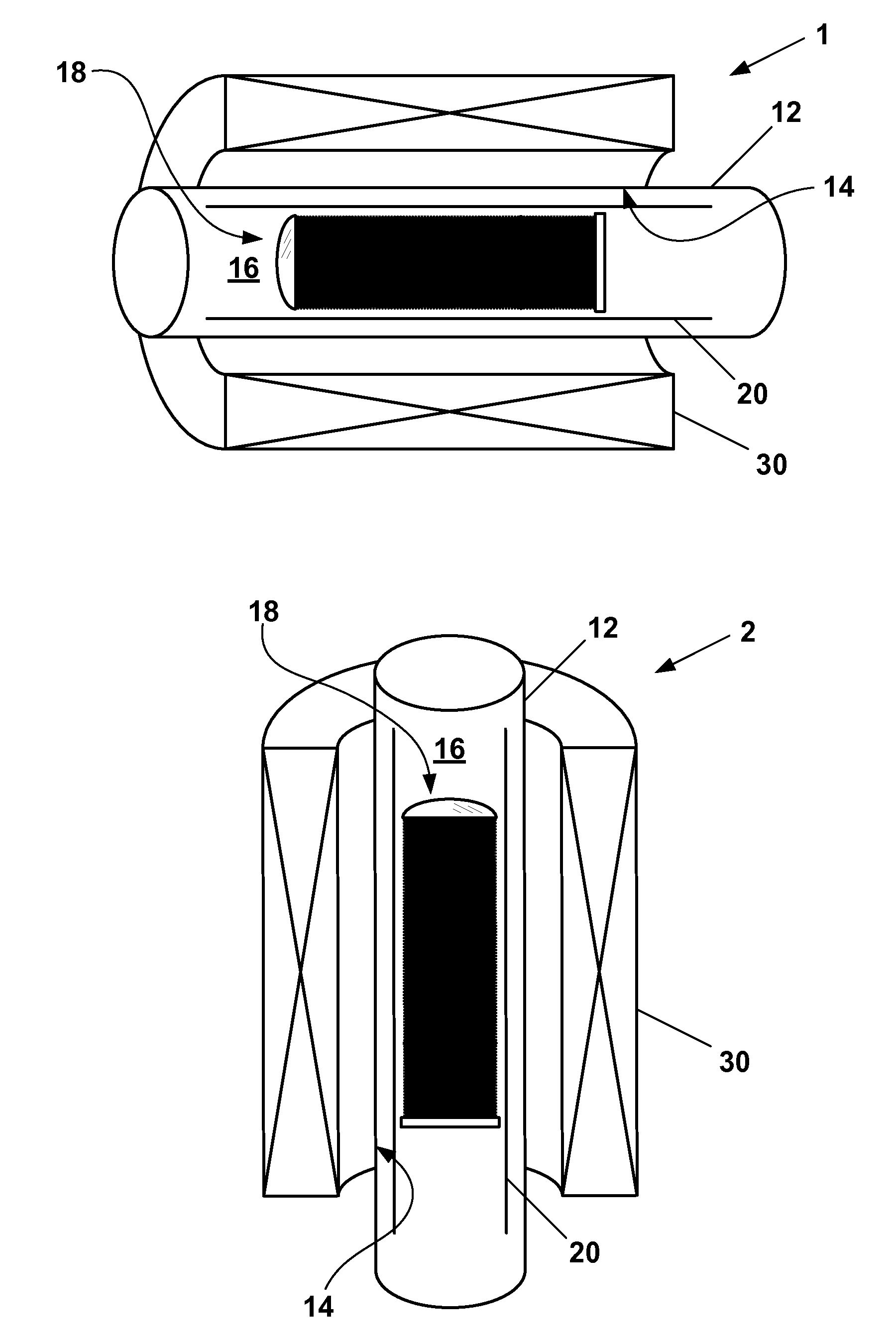
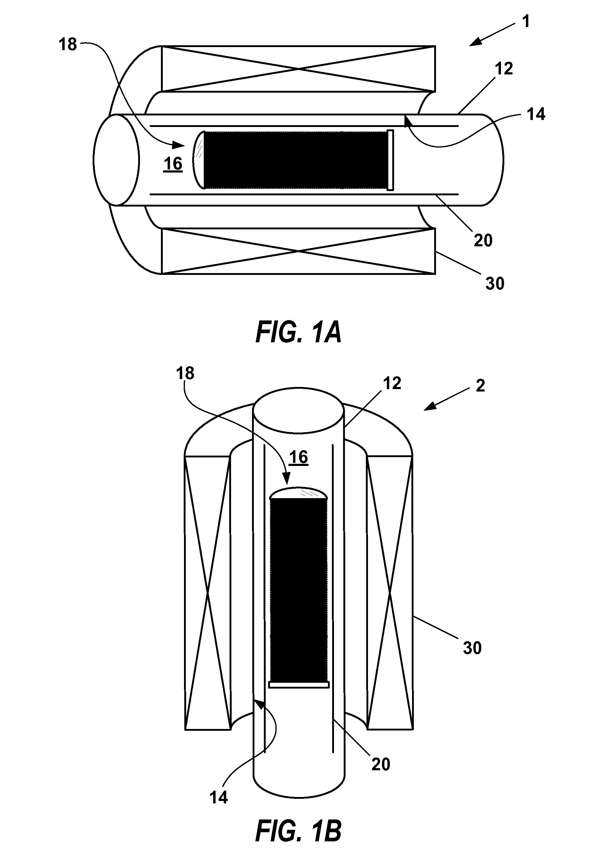
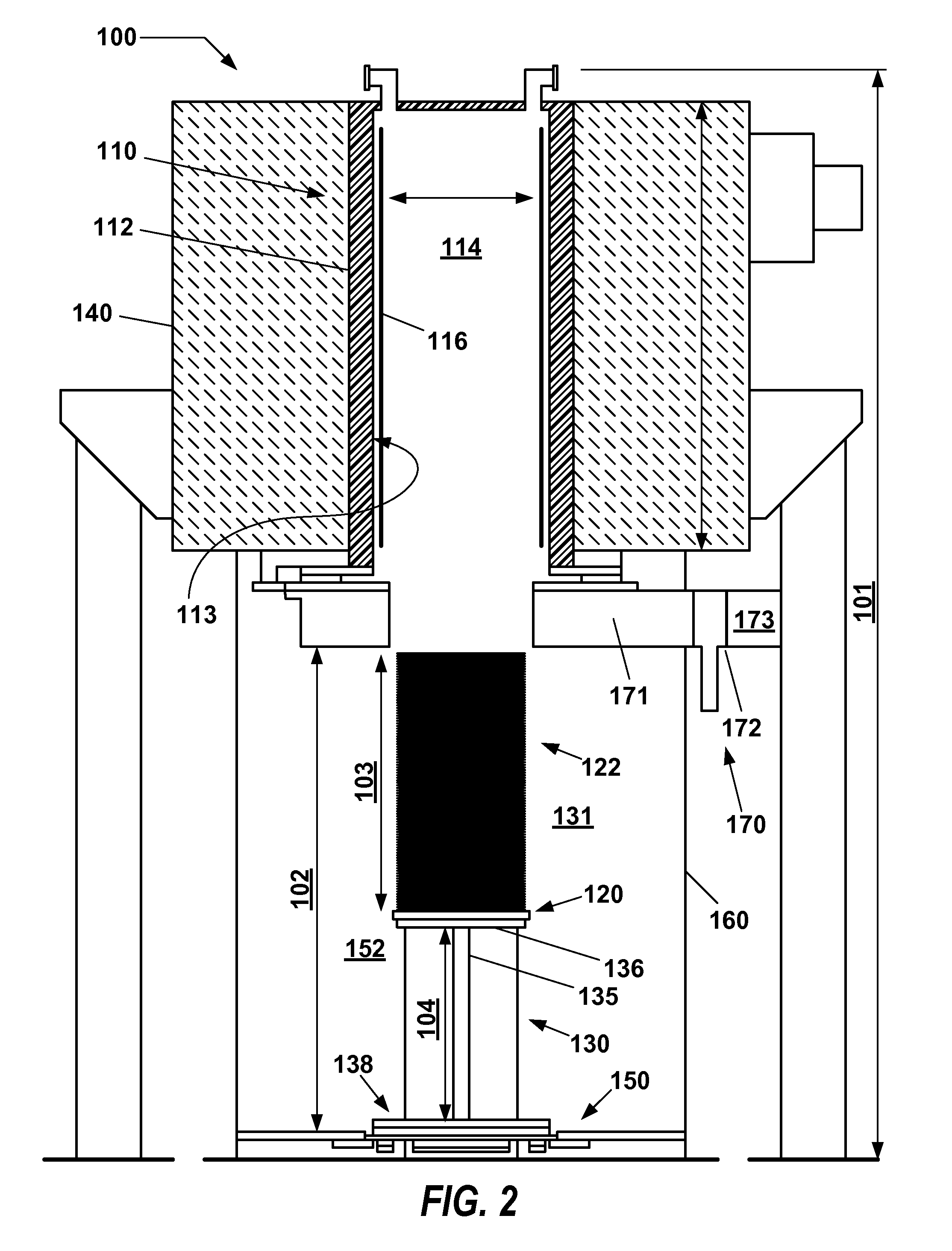
The invention relates to a system and method for annealing layers containing magnetic material on a microelectronic workpiece. This system includes a furnace with a vacuum chamber wall and a heating element assembly, which uses a non-metallic, anti-magnetic material to conduct heat. The system also includes a magnet system outside the furnace to generate a magnetic field within the processing space. The method involves loading workpieces into a boat, translating them into the furnace, and elevating their temperature while a magnetic field is applied. The technical effect of this invention is to provide a more efficient and effective method for annealing layers containing magnetic material on microelectronic workpieces.

Problems solved by technology

Conventionally, magnetic annealing systems have long temperature ramp-up and ramp-down cycle times, thus leading to reduced throughput.

Method used


Image

  • High rate magnetic annealing system and method of operating
  • High rate magnetic annealing system and method of operating
  • High rate magnetic annealing system and method of operating

Examples


Embodiment Construction

[0017]Systems and methods for annealing a microelectronic workpiece are described in various embodiments. One skilled in the relevant art will recognize that the various embodiments may be practiced without one or more of the specific details, or with other replacement and / or additional methods, materials, or components. In other instances, well-known structures, materials, or operations are not shown or described in detail to avoid obscuring aspects of various embodiments of the invention. Similarly, for purposes of explanation, specific numbers, materials, and configurations are set forth in order to provide a thorough understanding of the invention. Nevertheless, the invention may be practiced without specific details. Furthermore, it is understood that the various embodiments shown in the figures are illustrative representations and are not necessarily drawn to scale.

[0018]Reference throughout this specification to “one embodiment” or “an embodiment” means that a particular feat...


PUM

PropertyMeasurementUnit
Magnetic fieldaaaaaaaaaa
Reflectanceaaaaaaaaaa
Poweraaaaaaaaaa

Abstract

An annealing system and method of operating is described. The annealing system includes a furnace having a vacuum chamber wall that defines a processing space into which a plurality of workpieces may be translated and subjected to thermal and magnetic processing, wherein the furnace further includes a heating element assembly having at least one heating element located radially inward from the vacuum chamber wall and immersed within an outer region of the processing space, and wherein the heating element is composed of a non-metallic, anti-magnetic material. The annealing system further includes a magnet system arranged outside the vacuum chamber wall of the furnace, and configured to generate a magnetic field within the processing space.

Description

CROSS-REFERENCE TO RELATED APPLICATIONS[0001]Pursuant to 37 C.F.R. §1.78(a)(4), this application claims the benefit of and priority to co-pending U.S. Provisional Application No. 62 / 093,081 filed on Dec. 17, 2014, which is expressly incorporated by reference herein in its entirety.FIELD OF INVENTION[0002]The invention relates to an annealing system and method for processing a microelectronic workpiece, and in particular, a system and method for annealing one or more layers containing magnetic material on a microelectronic workpiece.BACKGROUND OF THE INVENTIONDescription of Related Art[0003]Magnetic annealing is one of three processes required to manufacture magnetoresistive random access memory (MRAM) devices compatible with conventional complementary metal oxide semiconductor (CMOS) logic based microelectronic workpieces. To successfully anneal a workpiece, the ferromagnetic layer must be held at a predetermined temperature in a magnetic field for a period of time long enough for t...

Claims


Application Information

Patent Timeline
IPC IPC(8): C21D9/00H01F41/02C21D1/26
CPCC21D9/0006H01F41/02C21D1/26C21D9/00H01F41/304
Inventor ISHII, TORUYAMAZAKI, MITSURU
Owner TOKYO ELECTRON LTD
Learn More