
Method and system for a gas turbine engine purge circuit water injection

a technology of purge circuit and purge fluid, which is applied in the direction of machines/engines, turbine/propulsion fuel valves, lighting and heating apparatus, etc., can solve the problems of fuel gas leakage, high cost, and risk of contact between the relatively high temperature purge air and the purge fluid

Inactive Publication Date: 2016-06-23
GENERAL ELECTRIC CO
View PDF8 Cites 19 Cited by
  • Summary
  • Abstract
  • Description
  • Claims
  • Application Information

AI Technical Summary

Benefits of technology

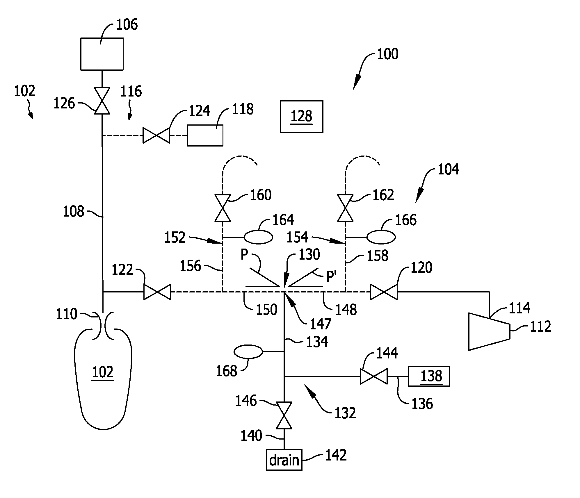
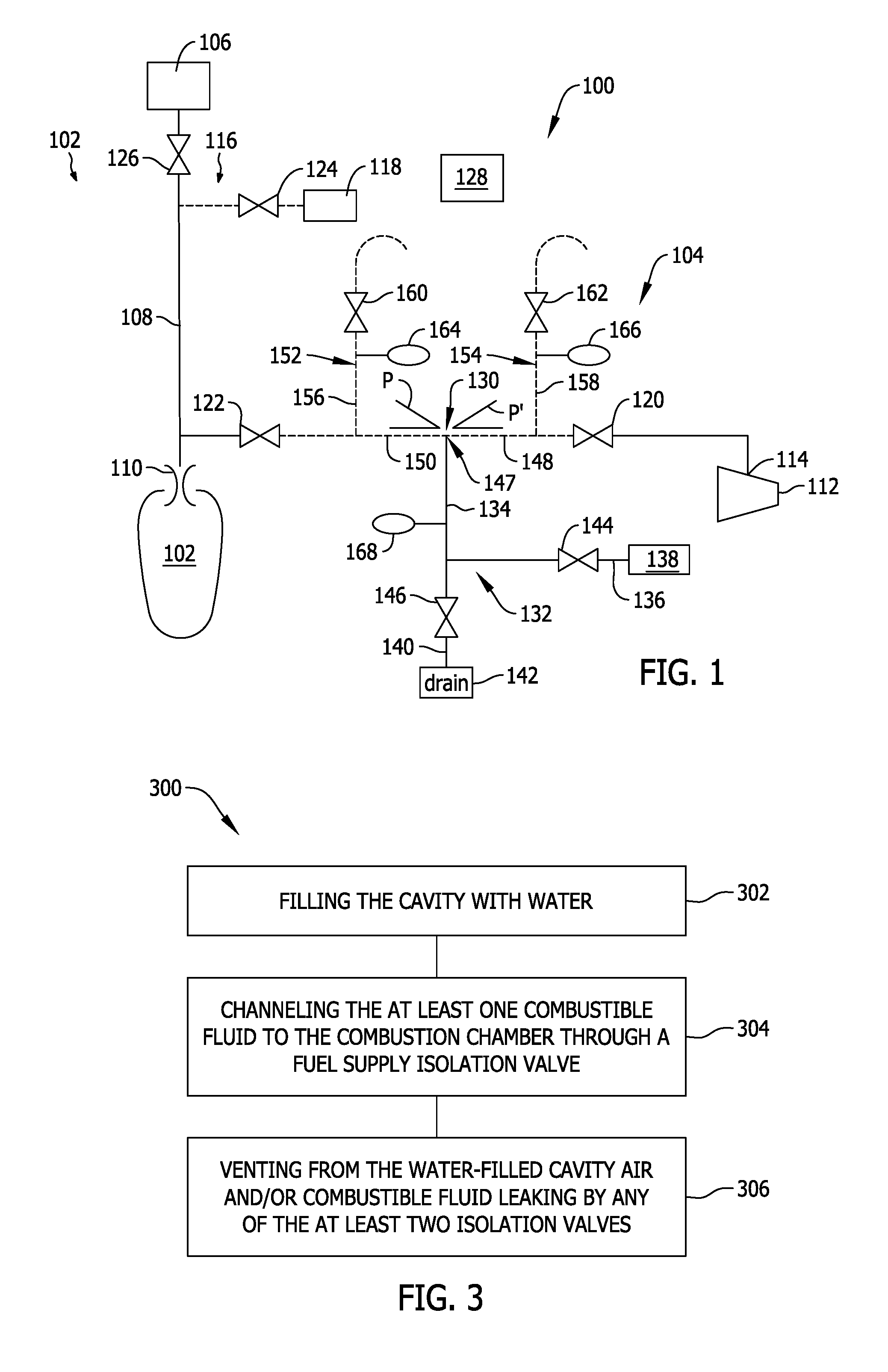
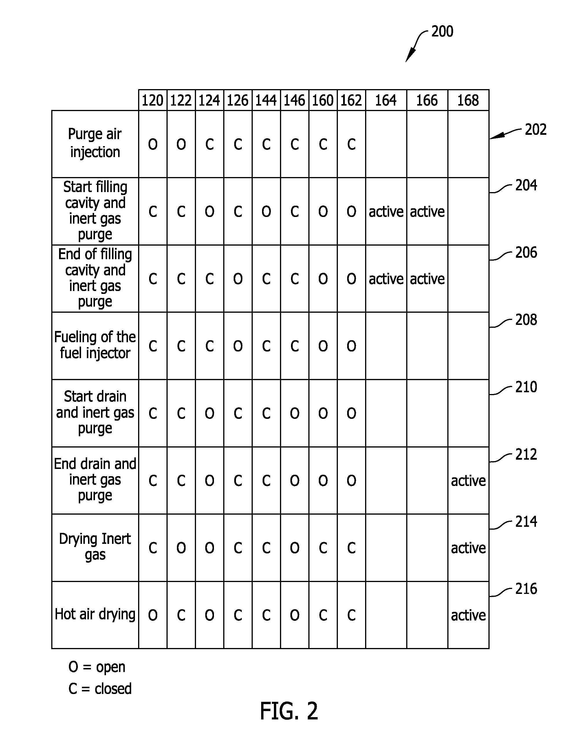
The patent text describes a fuel supply system for a gas turbine engine that includes a combustion chamber with a fuel injector and a purge circuit for purging the supply circuit. The purge circuit includes at least two isolation valves that define a cavity between them. The system also includes a water injection circuit for injecting water into the cavity and a cavity draining circuit for draining the water. The technical effects of this system include improved fuel efficiency, reduced emissions, and improved performance of the gas turbine engine.

Problems solved by technology

When the valves controlling the fuel or relatively high temperature air supply for purging are closed, there still is a risk, in some cases, of fuel gas leakage into the dead leg cavities formed by the isolation valves and, thus, a risk of contact between the relatively high temperature purge air, whose temperature may attain 500° C., and the fuel.
However, maintaining a high pressure of inert gas in the cavity may require an expensive compression system and may also consume a large quantity of inert gas to make-up for leakage through, for example, the isolation valves.
Maintenance of the block and bleed valves is conducted through physical inspection and / or through pressurization tests, which are laborious and require decommissioning of the turbine during the time period of the inspection or tests.

Method used


Image

  • Method and system for a gas turbine engine purge circuit water injection
  • Method and system for a gas turbine engine purge circuit water injection
  • Method and system for a gas turbine engine purge circuit water injection

Examples


Embodiment Construction

[0018]In the following specification and the claims, reference will be made to a number of terms, which shall be defined to have the following meanings.

[0019]The singular forms “a”, “an”, and “the” include plural references unless the context clearly dictates otherwise.

[0020]“Optional” or “optionally” means that the subsequently described event or circumstance may or may not occur, and that the description includes instances where the event occurs and instances where it does not.

[0021]Approximating language, as used herein throughout the specification and claims, may be applied to modify any quantitative representation that could permissibly vary without resulting in a change in the basic function to which it is related. Accordingly, a value modified by a term or terms, such as “about”, “approximately”, and “substantially”, are not to be limited to the precise value specified. In at least some instances, the approximating language may correspond to the precision of an instrument for...


PUM


Abstract

A method and fuel supply system for supply of a combustion chamber with at least one combustible fluid are provided. The fuel supply system includes a combustion chamber including a fuel injector, at least one supply circuit configured to supply the combustion chamber with a combustible fluid, and at least one purge circuit configured to purge the supply circuit, the purge circuit connected to a purge air source and the at least one supply circuit, the purge circuit including at least two isolation valves defining a cavity between the at least two isolation valves, the purge circuit including a water injection circuit configured to inject water into the cavity, the purge circuit including a cavity draining circuit configured to drain the cavity.

Description

CROSS REFERENCE TO RELATED APPLICATIONS[0001]This application claims the benefit of French Patent Application No. 1463235 filed on Dec. 23, 2014, the entirety of which is incorporated herein.BACKGROUND[0002]The field of the disclosure relates generally to gas turbine engines and, more particularly, to a system and method of supplying a purge fluid to a cavity of a fuel supply circuit.[0003]At least some known gas turbine engines include a compressor, one or more combustion chambers and an expansion turbine. The combustion chambers are supplied with gaseous fuel through a fuel supply system to be mixed therein with pressurized relatively high temperature air from the compressor. The fuel supply system permits several types of fuels, for example, natural gas, liquid fuel or synthetic gas or “syngas” to be supplied to the combustion chambers. The fuel supply system permits regulating a plurality of fuel supply system parameters from the fuel source to the one or more combustion chamber...

Claims


Application Information

Patent Timeline
Patent Type & Authority Applications(United States)
IPC IPC(8): F02M25/03F02M25/022F02M55/00F02M23/14F02C7/232F02C7/057
CPCF02M25/03F02C7/232F02M25/0227F02M55/007F02M23/14F02C7/057F02C7/22F23K5/16F23K5/18F05D2260/607F23K2300/203
Inventor MONTAGNE, PIERRE
Owner GENERAL ELECTRIC CO
Learn More