Opto-electric hybrid module

a hybrid module and opto-electric technology, applied in the direction of optical elements, instruments, optical waveguide light guides, etc., can solve problems such as liable to malfunction of opto-electric hybrid modules, and achieve the effects of reducing the thickness of the stack, excellent flexibility, and increasing the positioning accuracy of the mounting of optical elements

Active Publication Date: 2016-06-23
NITTO DENKO CORP
View PDF0 Cites 2 Cited by
  • Summary
  • Abstract
  • Description
  • Claims
  • Application Information

AI Technical Summary

Benefits of technology

[0015]In the inventive opto-electric hybrid module, the electric circuit is provided on the surface of the under-cladding layer of the optical waveguide, whereby the electric circuit body and the portion of the surface of the under-cladding layer other than the electric circuit formation portion can be covered with the stack including the core material layer and the over-cladding material layer. Even if the core material layer has a smaller thickness, i.e., even if the electric circuit body is not properly covered with the core material layer but the parts (e.g., edges) of the electric circuit body are uncovered, therefore, the uncovered parts of the electric circuit body can be properly covered with the over-cladding material layer in the subsequent over-cladding layer formation step. Thus, even if the thickness of the stack is reduced, the electric circuit body is prevented from being partly uncovered. Further, the surface portion of the stack present between the mounting pads and the electric circuit body, the surface portion shown as B of FIG. 1B, is located at a lower height position than the surface portion of the stack present on the electric circuit body, the surface portion shown as A of FIG. 1B, as measured from the surface of the under-cladding layer. With the synergistic effect of these arrangements, the inventive opto-electric hybrid module is excellent in flexibility.
[0016]Particularly, peripheral portions of the mounting pads are covered with the stack, and inner peripheral walls of the stack are formed on the peripheral portions of the mounting pads, which serve as positioning guides for positioning electrodes of the optical element. Thus, the electrodes of the optical element can be guided by the positioning guides to be respectively positioned on center portions of the mounting pads. In this case, the positioning accuracy for the mounting of the optical element can be increased, thereby improving the light transmission efficiency between the optical element and the core.

Problems solved by technology

With the electric circuit body 4 partly uncovered, short circuit is liable to occur, so that the opto-electric hybrid module is liable to malfunction.

Method used


Image

  • Opto-electric hybrid module
  • Opto-electric hybrid module
  • Opto-electric hybrid module

Examples


example 1

Conventional Example 1

[0045]An opto-electric hybrid module shown in FIG. 4 was produced in substantially the same manner as in the Example, except that a cover lay was formed from a photosensitive polyimide resin as having a film thickness of 4 μm.

example 2

Conventional Example 2

[0046]An opto-electric hybrid module shown in FIG. 5 was produced in substantially the same manner as in the

[0047]Example, except that the over-cladding layer covering the electric circuit body had a film thickness of 4 μm.

Evaluation for Film Thickness of Electric Circuit Body Covering Portion in Section

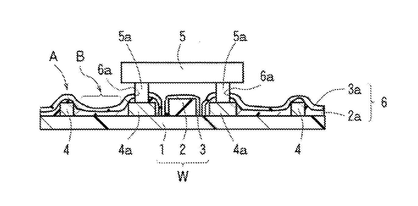
[0048]The opto-electric hybrid modules of the Example and Conventional Examples 1 and 2 were each cut perpendicularly to the electric circuit body, and the electric circuit body was checked for partially uncovered portions thereof. As a result, it was found that the opto-electric hybrid module of the Example was free from uncovered portions of the electric circuit body but the opto-electric hybrid modules of Comparative Examples 1 and 2 suffered from the uncovered portions of the edges of the electric circuit body. These results indicate that the Example is more excellent in reliability than Conventional Examples 1 and 2.

[0049]A material for the over-cladding la...


PUM


Abstract

An opto-electric hybrid module is provided which has a linear light-path core and an electric circuit including mounting pads and an electric circuit body provided on a surface of an under-cladding layer of an optical waveguide. An optical element is mounted with its electrodes in abutment against the mounting pads. The electric circuit body and a portion of the surface of the under-cladding layer other than a core formation portion and an electric circuit formation portion are covered with a stack including a core material layer and an over-cladding material layer. A surface portion of the stack present between the mounting pads and the electric circuit body is located at a lower height position than a surface portion of the stack present on the electric circuit body.

Description

TECHNICAL FIELD[0001]The present invention relates to an opto-electric hybrid module which includes an optical waveguide, an electric circuit provided directly on the optical waveguide, and an optical element (a light emitting element or a light receiving element) mounted on the electric circuit.BACKGROUND ART[0002]Opto-electric hybrid modules are typically produced by: individually producing a flexible circuit board including an electric circuit provided on a surface of an insulation layer, and an optical waveguide including an under-cladding layer, a core and an over-cladding layer stacked in this order; bonding a back surface of the insulation layer of the flexible circuit board to a surface of the over-cladding layer of the optical waveguide with an adhesive agent; and mounting an optical element on a predetermined portion (mounting pads) of the electric circuit. The electric circuit has a rectangular sectional shape. The opto-electric hybrid modules are flexible, and are advant...

Claims


Application Information

Patent Timeline
Patent Type & Authority Applications(United States)
IPC IPC(8): G02B6/42G02B6/13G02B6/122
CPCG02B6/4281G02B6/13G02B6/122G02B6/4214G02B6/4274G02B6/43G02B6/138H01L2224/16225
Inventor TANAKA, NAOYUKIISHIMARU, YASUTOSHIBATA, NAOKITSUJITA, YUICHI
Owner NITTO DENKO CORP
Why Eureka
Try Eureka