Eureka AIR delivers breakthrough ideas for toughest innovation challenges, trusted by R&D personnel around the world.

Wireless inductive power transfer

a technology of inductive power transfer and wireless, which is applied in the direction of inductance, transformer, transportation and packaging, etc., can solve the problems of inconvenient use, inability to easily replace or recharge batteries, and bulk, so as to reduce the impact of power transfer signal, improve communication, and reduce interference

Active Publication Date: 2016-06-23
KONINKLJIJKE PHILIPS NV
View PDF0 Cites 53 Cited by
  • Summary
  • Abstract
  • Description
  • Claims
  • Application Information

AI Technical Summary

Benefits of technology

The invention improves communication and makes power transfer systems more reliable and safe. It can protect against unintended operation caused by other communication candidates.

Problems solved by technology

Traditionally, this has been achieved using batteries located in the devices but this approach has a number of disadvantages including extra weight, bulk and the need to frequently replace or recharge the batteries.
However, this tends to be impractical and requires the user to physically insert connectors or otherwise establish a physical electrical contact.
It also tends to be inconvenient to the user by introducing lengths of wire.
Although, internal batteries may prevent the need for a wired connection to an external power supply, this approach only provides a partial solution as the batteries will need recharging (or replacing which is expensive).
The use of batteries may also add substantially to the weight and potentially cost and size of the devices.
However, a limitation of the Qi system is that it does not support communication from the power transmitter to the power receiver.
In general, communication between power receiver and power transmitter is faced with multiple challenges and difficulties.
In particular, there is typically a conflict between the requirements and characteristics for the power signal in transferring power and the requirements and preferences for the communication.
However, using the power signal itself for not only performing a power transfer but also for carrying information results in difficulties due to the varying operating characteristics.
However, this cannot be guaranteed in many applications.
E.g., if wireless power transfer is to be used to power a motor driven appliance (such as e.g. a blender), the motor current tends to be quite erratic and discontinuous.
This results in the amplitude of the current in the transmitter also changing with the load.
This load variation will interfere with the load modulation, resulting in degraded communication.
Indeed, in practice it is typically very difficult to detect load modulation for loads that include a motor as part of the load.
Therefore, in such scenarios, the number of communication errors is relatively high or the communication may utilize a very high data symbol energy, thereby reducing the possible data rate very substantially.
However, there are also disadvantages associated with using an independent communication link.
For example, the use of separate communication channels could result in interference between the operations of different power transfers which could result in a potentially dangerous situation with high power levels.
For example, the control operations may interfere with each other, e.g. by the control data from the power receiver of one power transfer operation being used to control the power transfer to another nearby power receiver The separation between communication and power transfer signals may result in less robust and less fail safe operation.
Another potential problem with wireless power transfer is that power may unintentionally be transferred to unintended e.g. metallic objects.
The heat increase may be very significant and may indeed result in a risk of pain and damage to humans subsequently picking up the objects.
For comparison, skin burning caused by contact with hot objects starts at temperatures of around 65° C. The experiments have indicated that a power absorption of 500 mW or more in a typical foreign object rises its temperature to an unacceptable level.
For example, a foreign object may be positioned on or near the power transmitter resulting in this being heated due to the power signal.
It is substantially more difficult to determine the transmitted and received power estimates sufficiently accurately at higher power levels than for lower power levels.
Thus, whereas such accuracy may be acceptable for a low power transfer operation it is not acceptable for a high power transfer operation.
This is particularly difficult at high power levels, and frequently it is difficult for power receivers to generate estimates that are sufficiently accurate.
However, if the power receiver overestimates the received power, this can result in power consumption by foreign objects not being detected.
Conversely, if the power receiver underestimates the received power, this may lead to false detections where the power transmitter terminates the power transfer despite no foreign objects being present.
Thus, the current approaches for foreign object detection and communication may be suboptimal and have some associated disadvantages.

Method used


Image

  • Wireless inductive power transfer
  • Wireless inductive power transfer
  • Wireless inductive power transfer

Examples


Embodiment Construction

[0103]The following description focuses on embodiments of the invention applicable to a Qi power transfer system but it will be appreciated that the invention is not limited to this application but may be applied to many other power transfer systems.

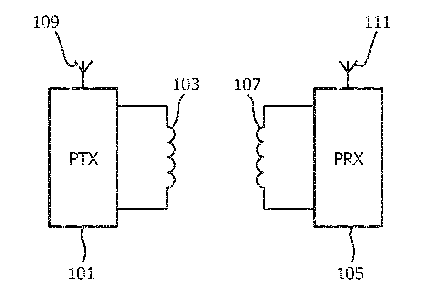
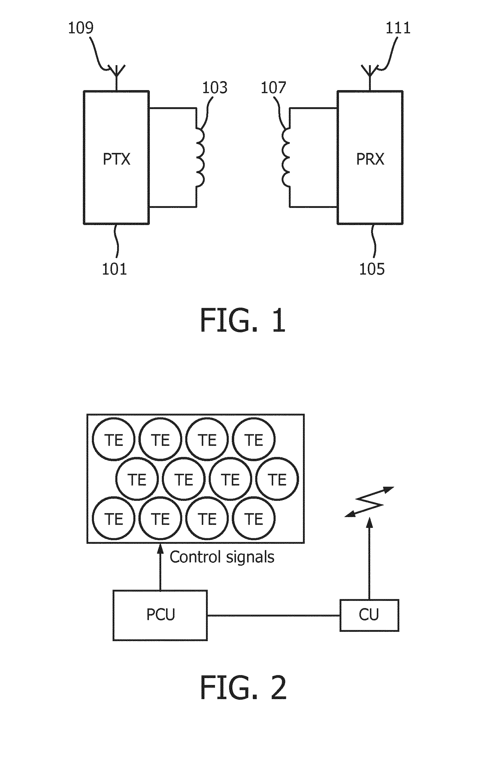
[0104]FIG. 1 illustrates an example of a power transfer system in accordance with some embodiments of the invention. The power transfer system comprises a power transmitter 101 which includes (or is coupled to) a transmit power transfer coil / inductor which henceforth will be referred to as the transmitter coil 103. The system further comprises a power receiver 105 which includes (or is coupled to) a receive power transfer coil / inductor which henceforth will be referred to as the receiver coil 107.

[0105]The system provides a wireless inductive power transfer from the power transmitter 101 to the power receiver 105. Specifically, the power transmitter 101 generates a power transfer signal which is propagated as a magnetic flux by the trans...


PUM


Abstract

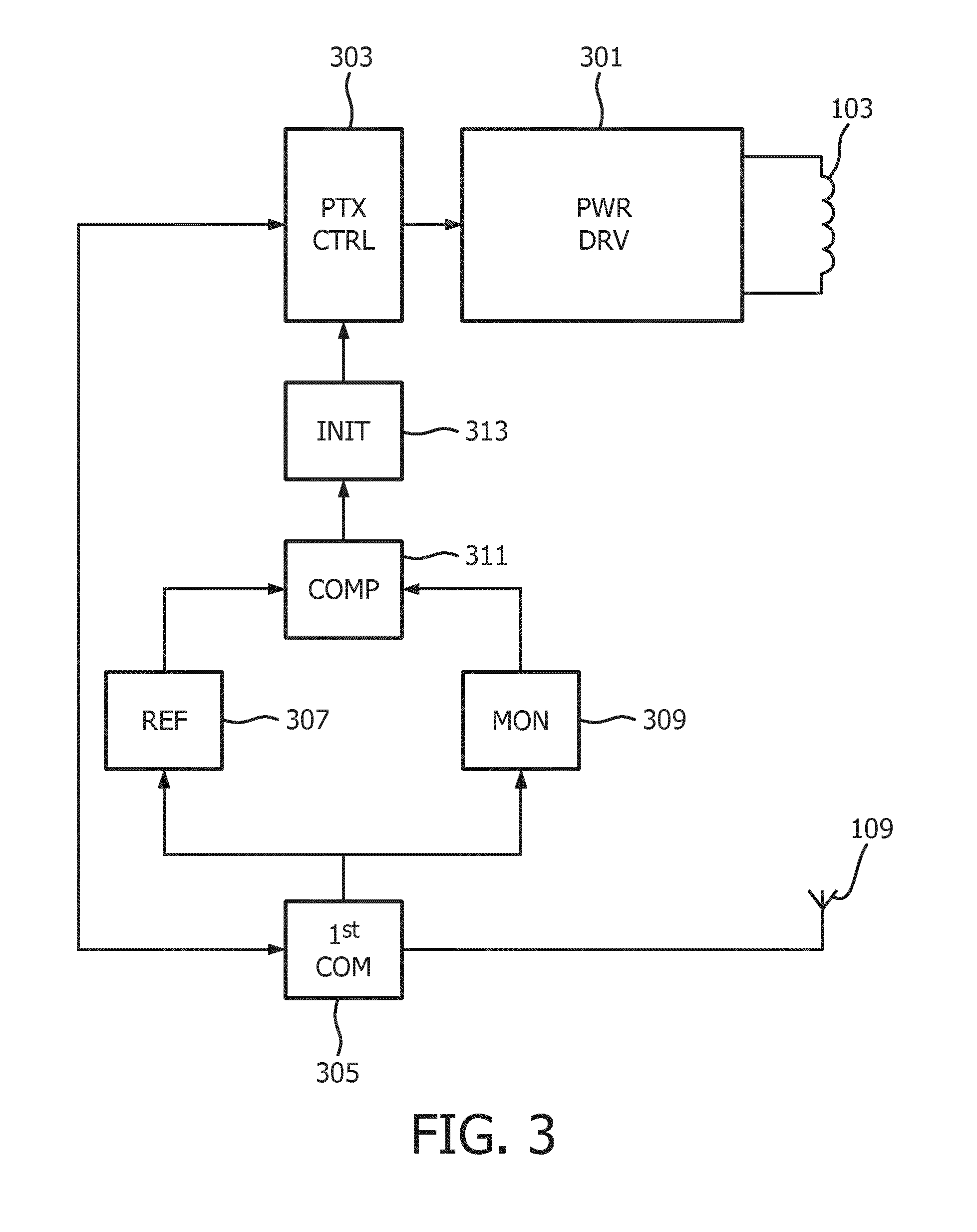
A wireless power transfer system includes a power receiver (105) and a power transmitter (101) generating a wireless inductive power transfer signal for powering the power receiver (105) during a power transfer phase. An apparatus, often the power transmitter (101) comprises a first communication unit (305) communicating with a second communication unit of an entity using an electromagnetic communication signal. The entity may typically be the power receiver (105). The apparatus comprises a reference processor (307) for measuring and storing a reference value of a characteristic of the communication signal and a measurement unit (309) which repeatedly during the power transfer phase determines a measured value of the characteristic. A comparator (311) compares the measured values to the reference value and an initiator (313) triggers an entity detection process if the comparison indicates that a measured value and the reference value do not meet a similarity criterion. The entity detection process detect a presence of another entity.

Description

FIELD OF THE INVENTION[0001]The invention relates to inductive power transfer and in particular, but not exclusively, to an inductive power transfer system compatible with the Qi wireless power transfer standard.BACKGROUND OF THE INVENTION[0002]Many systems require a wiring and / or electrical contacts in order to supply electrical power to devices. Omitting these wires and contacts provides for an improved user experience. Traditionally, this has been achieved using batteries located in the devices but this approach has a number of disadvantages including extra weight, bulk and the need to frequently replace or recharge the batteries. Recently, the approach of using wireless inductive power transfer has received increasing interest.[0003]Part of this increased interest is due to the number and variety of portable and mobile devices having exploded in the last decade. For example, the use of mobile phones, tablets, media players etc. has become ubiquitous. Such devices are generally p...

Claims


Application Information

Patent Timeline
Patent Type & Authority Applications(United States)
IPC IPC(8): H02J5/00H02J7/02H02J50/60H04B5/00H04B5/48H02J50/00H02J50/10H02J50/40H02J50/80
CPCH02J5/005H04B5/0037H01F38/14H02J50/60H02J7/025H02J50/10H02J50/12H02J50/80H02J50/402H04B5/24H04B5/72H04B5/79
Inventor JOYE, NEIL FRANCISVAN WAGENINGEN, ANDRIESETTES, WILHELMUS GERARDUS MARIA
Owner KONINKLJIJKE PHILIPS NV
Why Eureka
Eureka Blog
Learn More