Flyback converter output current evaluation circuit and evaluation method

a technology of output current and evaluation circuit, which is applied in the direction of electric variable regulation, process and machine control, instruments, etc., can solve the problem of accurate evaluation of output current supplied to the load

Active Publication Date: 2016-06-23
ALPHA & OMEGA SEMICON CAYMAN
View PDF7 Cites 25 Cited by
  • Summary
  • Abstract
  • Description
  • Claims
  • Application Information

AI Technical Summary

Problems solved by technology

However, there is a problem in accurate evaluation of output current supplied to the load, especially under conditions of continuous conduction mode (CCM) and discontinuous conduction mode (DCM).

Method used


Image

  • Flyback converter output current evaluation circuit and evaluation method
  • Flyback converter output current evaluation circuit and evaluation method
  • Flyback converter output current evaluation circuit and evaluation method

Examples


Embodiment Construction

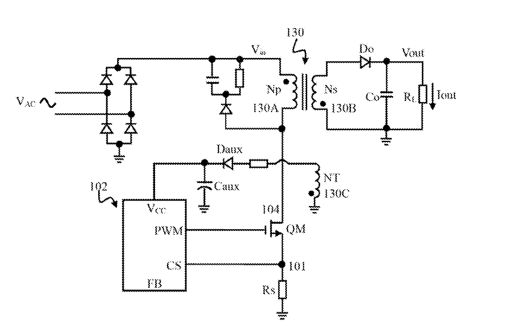
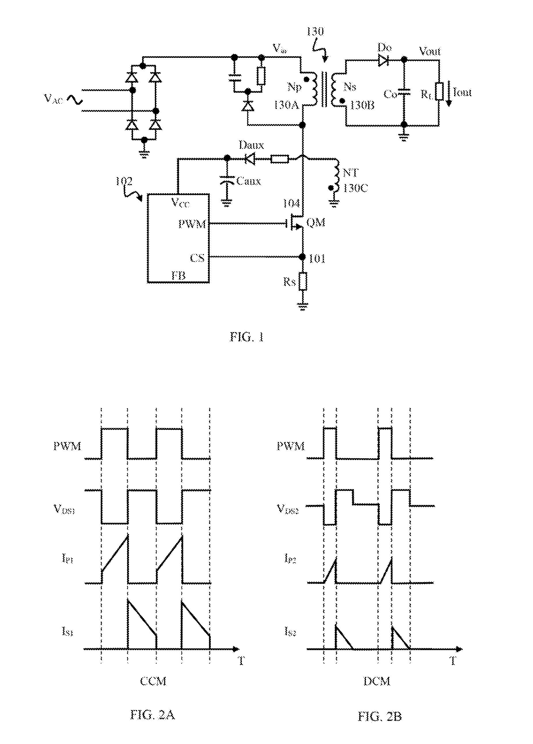
[0015]FIG. 1 shows a circuit configuration of a flyback converter according to an embodiment of the present invention. Main switch QM for control current flowing through primary side of transformer 130 may be a power MOSFET with a drain used as an input terminal, a source used as a output terminal and a gate used as a control terminal. The control terminal of the main switch QM receives a control signal produced by a main control module 102 and correspondingly turns on / off the main switch QM that controls current flowing through the primary winding 130A of transformer 130 in the flyback convertor to transfer energy from primary side to secondary side. The primary winding 130A receives a DC input voltage VIN, which may be obtained by rectification of an AC voltage VAC via a bridge rectifier. Transformer 130 also has a secondary winding 130B for delivering an output voltage VOUT, and an auxiliary winding 130C for detecting the state of voltage generated by the secondary winding 130B. ...


PUM


Abstract

An output current calculating circuit for a flyback converter operating under CCM and DCM is disclosed. The off current value ION and the blanking current value ILEB flowing through a sensing resistor are calculated using a detection module and are summed together using a current summing unit. A voltage converted from the sum value of the off current value IOFF and the blanking current value ILEB is transmitted through an output stage in a predetermined time ratio of a cycle with the duty cycle determined by a logic control unit, in which the logic control unit controls the output stage to receive the voltage converted from sum current in a predetermined time period of each cycle, and prevents the output stage to receive the voltage converted from sum current in the remaining time other than such predetermined time period of each cycle.

Description

CROSS-REFERENCE TO RELATED APPLICATIONS[0001]This application claims the priority benefit of a Chinese patent application number 201410790883.0 filed Dec. 17, 2014 by a common inventor of this application. The entire Disclosure made in the Chinese patent application number 201410790883.0 is hereby incorporated by reference.FIELD OF THE INVENTION[0002]The present invention relates to power conversion systems, specifically, relates to the device and method for detection and evaluation of output current of a flyback converter in a power supply to obtain an accurate evaluation of output current.BACKGROUND OF RELATED ART[0003]Conventional power conversion systems usually use power supply switching in constant voltage or constant current control mode. In a power conversion system, turning on or off of control switching elements on the primary winding of a transformer periodically generates currents on the winding passing through the switching elements, thus energy on the primary side is t...

Claims


Application Information

Patent Timeline
Patent Type & Authority Applications(United States)
IPC IPC(8): H02M3/335G01R19/15G01R19/10
CPCH02M3/33507G01R19/15G01R19/10H02M1/0009G01R19/25H02M1/08H02M3/33515
Inventor CHEN, YU-MINGCHENG, JUNG-PEIHUANG, PEI-LUN
Owner ALPHA & OMEGA SEMICON CAYMAN
Why Eureka
Try Eureka