
Capacitance-to-digital converter utilizing digital feedback and auxiliary dac

a technology of capacitive to digital converter and digital feedback, applied in the direction of code conversion, instruments, electrochemical variables, etc., can solve the problems of reducing the accuracy performance of amplifiers, often posing performance limitations, etc., and achieve the effect of reducing the impact of amplifier nonidealities on performan

Active Publication Date: 2016-06-23
SILICON LAB INC
View PDF0 Cites 7 Cited by
  • Summary
  • Abstract
  • Description
  • Claims
  • Application Information

AI Technical Summary

Benefits of technology

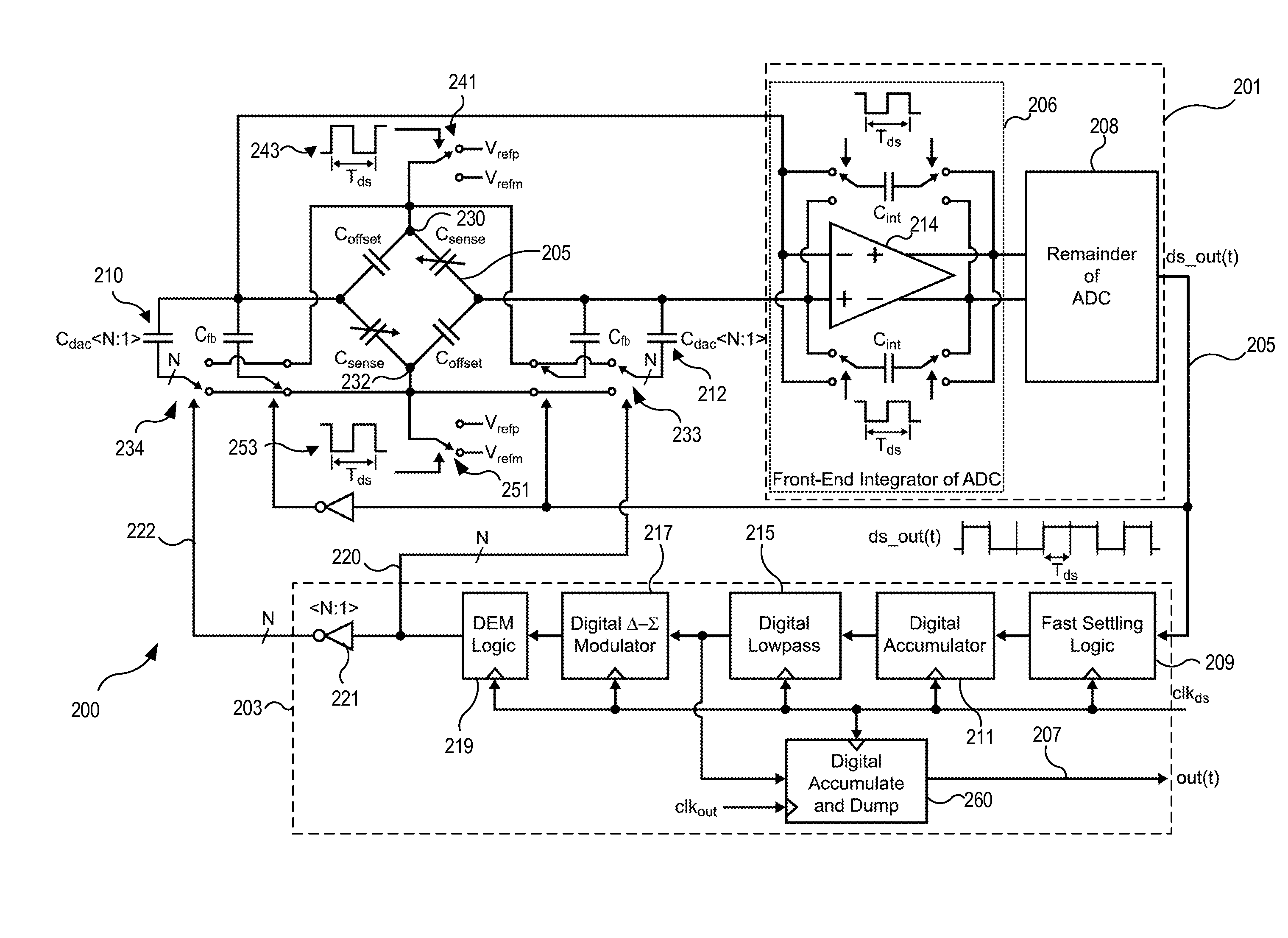
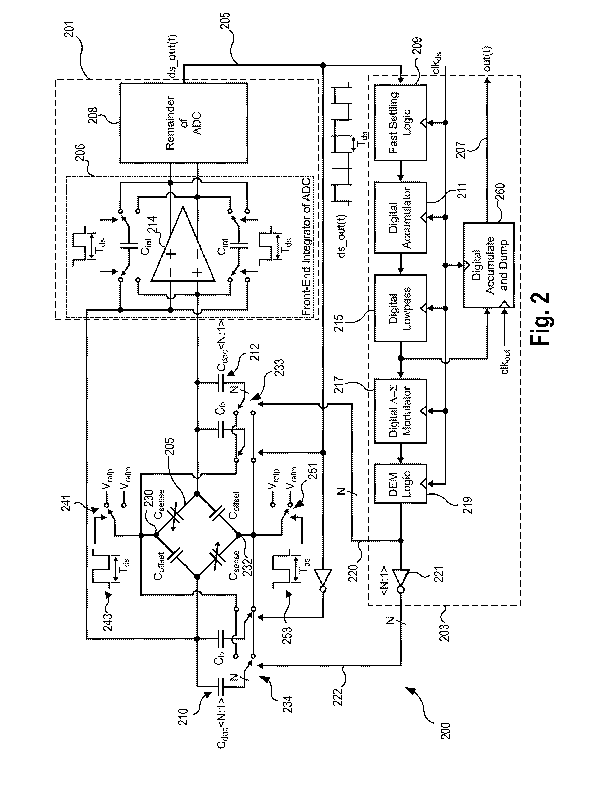
The patent describes a circuit that uses a digital feedback network to reduce the impact of amplifier nonidealities on the performance of a capacitance-to-digital converter. A capacitor bridge circuit senses a difference in capacitance between sense capacitors and other capacitors in the circuit and uses auxiliary capacitor digital to analog converters (DACs) to reduce the sensed difference. An analog to digital converter (ADC) converts the signal generated by the bridge circuit to a digital signal, and a digital accumulator creates an accumulated digital signal based on the digital signal. The auxiliary capacitor DACs are controlled to offset the difference in capacitance between the sense capacitors and other capacitors in the bridge circuit based on the accumulated digital signal. The technical effect of this invention is to improve the performance of the capacitance-to-digital converter by reducing the impact of amplifier nonidealities.

Problems solved by technology

These amplifiers often pose performance limitations due to their finite DC gain, nonlinear gain characteristic, and limited output swing.
The finite DC gain and nonlinear gain characteristic of the amplifier can lead to nonlinearity in the capacitance-to-digital measurement characteristic, which degrades its accuracy performance.

Method used


Image

  • Capacitance-to-digital converter utilizing digital feedback and auxiliary dac
  • Capacitance-to-digital converter utilizing digital feedback and auxiliary dac
  • Capacitance-to-digital converter utilizing digital feedback and auxiliary dac

Examples


Embodiment Construction

[0007]Accordingly, in an embodiment, the use of a digital feedback network reduces the impact of amplifier nonidealities on the performance of the capacitance-to-digital converter.

[0008]In one embodiment, a capacitance-to-digital converter circuit includes a capacitor bridge circuit to sense a difference in capacitance between one or more sense capacitors and other capacitors in the bridge circuit. Auxiliary capacitor digital to analog converters (DACs) are coupled to the capacitor bridge circuit to reduce the sensed difference observed at the output of the bridge circuit. An analog to digital converter (ADC) receives a signal generated by the capacitor bridge circuit and the auxiliary capacitor DACs and converts the received signal to a digital signal. A digital accumulator creates an accumulated digital signal based on the digital signal supplied by the ADC. The auxiliary capacitor DACs are controlled to offset a difference in capacitance between the one or more sense capacitors a...


PUM


Abstract

A capacitance-to-digital converter circuit s a capacitor bridge circuit to sense a difference in capacitance between sense capacitors and fixed capacitors in the bridge circuit. The sense capacitors vary according to a sensed parameter. Auxiliary capacitor digital to analog converters (DACs) are coupled to the capacitor bridge circuit to cancel the sensed difference. An analog to digital converter (ADC) receives a signal generated by the capacitor bridge circuit and the auxiliary capacitor DACs and converts the received signal to a digital signal. A digital accumulator accumulates the ADC output, whose output represents the difference in capacitance between the sense capacitors and the fixed capacitors. The accumulator output is used to control the auxiliary capacitor DACs to offset the difference in capacitance between the sense capacitors and the fixed capacitors. The accumulator output also provides the basis for the capacitance-to-digital circuit output.

Description

CROSS-REFERENCE TO RELATED APPLICATION(S)[0001]This application relates to the applications entitled “Circuit Including a Switched Capacitor Bridge and Method,” application Ser. No. 13 / 925,781, flied on Jun. 24, 2013, naming Louis Nervegna et. al., as inventors; and the application entitled “Capacitance to Digital Converter”, application Ser. No. 13 / 954,955, filed on Jul. 30, 2013, naming Louis Nervegna et. al., as inventors, which applications are incorporated herein by reference.BACKGROUND[0002]1. Field of the Invention[0003]This invention relates to capacitive-to-digital converters, and more particularly to capacitive-to-digital converters to sense a parameter using a bridge circuit.[0004]2. Description of the Related Art[0005]Capacitance-to-digital conversion plays an important role in many sensor applications such as measurement of pressure and humidity. In these sensing applications, key performance metrics include measurement range, resolution (i.e. rms noise of each measurem...

Claims


Application Information

Patent Timeline
IPC IPC(8): H03M3/00
CPCH03M3/362H03M3/496H03M3/476H03M3/464G01D5/24G01R17/105G01R27/2605G01N27/26
Inventor PERROTT, MICHAEL H.NERVEGNA, LOUIS
Owner SILICON LAB INC
Learn More