
Tube alignment functionality for mobile radiography systems

a mobile radiography and functionality technology, applied in the field of imaging systems, can solve the problems of not living up to the expectations of image quality and/or radiation dosage of mobile imagers

Active Publication Date: 2016-06-30
KONINKLJIJKE PHILIPS NV
View PDF26 Cites 12 Cited by
  • Summary
  • Abstract
  • Description
  • Claims
  • Application Information

AI Technical Summary

Benefits of technology

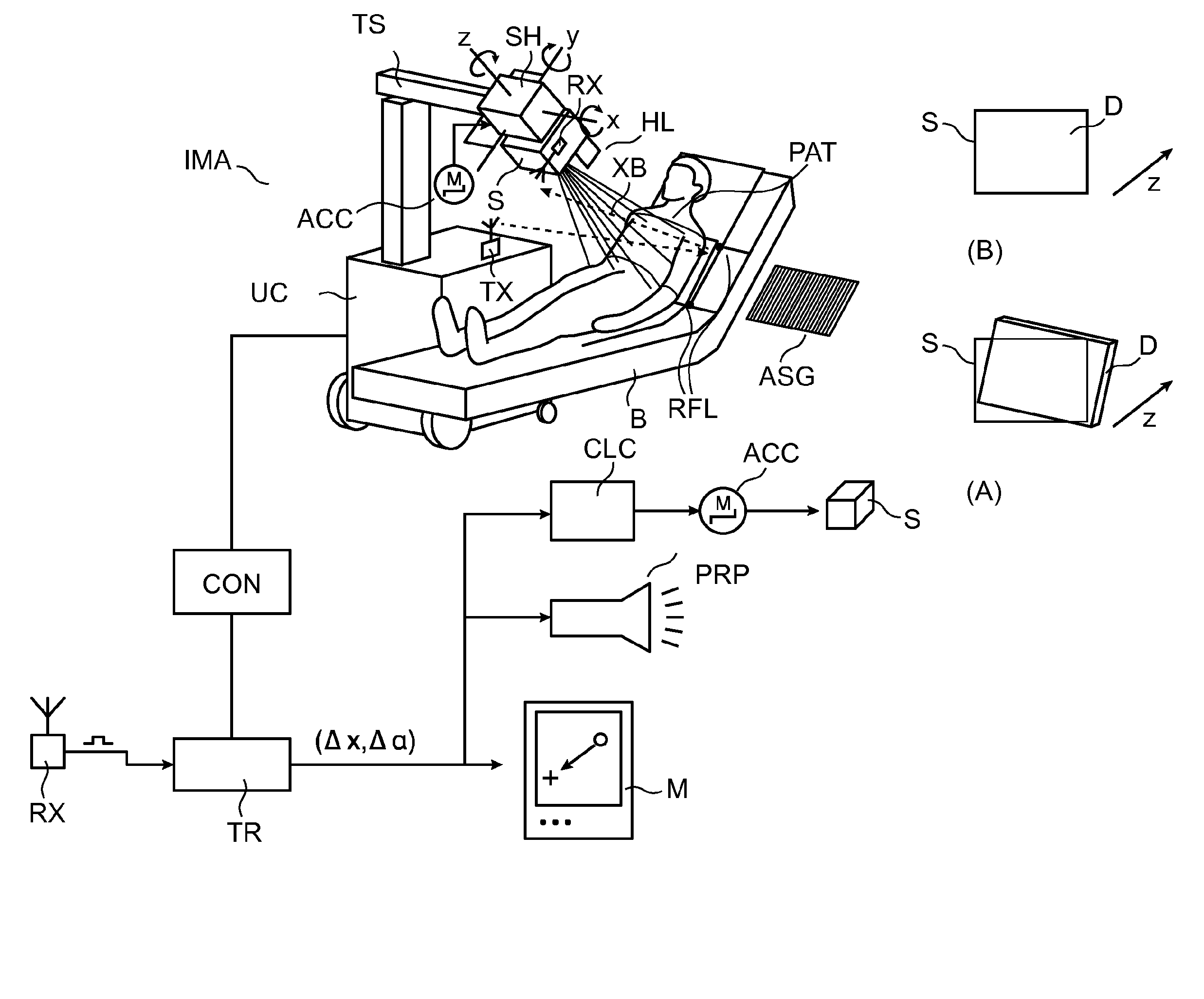
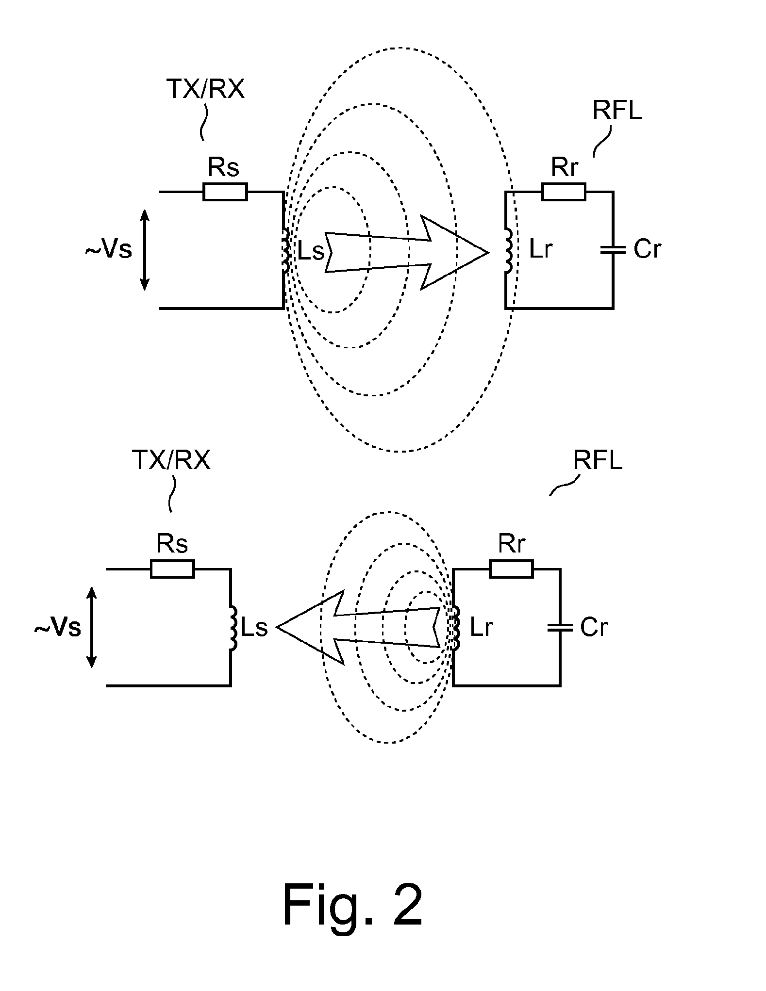
The system proposed in this patent operates on radio waves, rather than visible light, which means there is no need for line of sight between the detector and the tube. This solves the problem of optical occlusion in mobile X-ray systems. The precise positioning and alignment of the detector and tube can be achieved, resulting in better image quality and reduced retakes. The system uses a reflector that resonates at a different frequency for each detector, allowing for more precise positioning. The reflectors can be arranged in a phased array to resolve for 6 degrees of freedom. This technology addresses the challenges of positioning and aligning X-ray systems in medical applications.

Problems solved by technology

It has been however noted that, on occasion, such mobile imagers do not live up to expectations in terms of image quality and / or incurred radiation dosage.

Method used


Image

  • Tube alignment functionality for mobile radiography systems
  • Tube alignment functionality for mobile radiography systems
  • Tube alignment functionality for mobile radiography systems

Examples


Embodiment Construction

[0058]With reference to FIG. 1 there is shown an arrangement including a mobile X-ray imaging apparatus IMA. According to one embodiment, the apparatus is of the “dolly type” and comprises an undercarriage UC on rollers so as to be position-able at a convenient location relative to a patient PAT. The imager IMA is mobile in the sense that it is not permanently installed at a fixed place such as a room, but can be moved about from location to location as desired. One possible clinical application (as exemplary indicated in FIG. 1) is bedside chest X-ray but other uses are also envisaged for instance, in A&E, where X-ray images are frequently required of other body parts such as a patient's hand, foot, leg or head if an examination for injuries is called for.

[0059]There is an operator console CON built into the undercarriage for clinical personnel (in the following referred to as operator or user) to operate imager 100. Console CON allows user to control image acquisition by releasing...


PUM


Abstract

An X-ray imager having a navigation-aid subsystem including one or more transmitters (TX), one or more receivers (RX) and one or more reflectors (RFL). A radio signal is transmitted by transmitter(TX), is then reflected off reflector RFL and is then received at receiver (RX). The received signal is then resolved into positional correction information that can be used to guide a motion of the imager's tube (S) and or detector (D) to position and / or align the tube (S) and / or detector (D) relative to each other in a desired spatial configuration to ensure optimal imaging results. The imager may be a mobile imaging system with the detector (D) portable.

Description

FIELD OF THE INVENTION[0001]The invention relates to an imaging system, to a related method, to a computer program element, and to a computer readable medium.BACKGROUND OF THE INVENTION[0002]Medical personnel in intensive care units or in A & E (Accident and Emergency) departments have come to rely more and more on mobile X-ray imagers for flexible radiography. Mobile X-ray imagers afford acquisition of X-ray images even under awkward, adverse conditions or can be used in different locations. The imager is in other words not permanently installed in a particular X-ray examination room or location as more traditional imaging systems are. Another use scenario for mobile X-ray imagers is for instance in care homes. Elderly patients who have been bed-ridden for long will need to have a chest X-ray taken, sometimes every day, to monitor for possible build-up of water in their lungs which could lead to pneumonia.[0003]It has been however noted that, on occasion, such mobile imagers do not...

Claims


Application Information

Patent Timeline
IPC IPC(8): A61B6/00
CPCA61B6/587A61B6/4405A61B6/461A61B6/4452A61B6/08A61B6/588
Inventor MEHENDALE, ADITYAVAN DE VEN, RICHARD JOHANNES MARIAMANKE, DIRKKURZE, CHRISTOPH
Owner KONINKLJIJKE PHILIPS NV
Learn More