Cutting fluid tank

Inactive Publication Date: 2016-06-30
OKUMA CORP
View PDF13 Cites 4 Cited by
  • Summary
  • Abstract
  • Description
  • Claims
  • Application Information

AI Technical Summary

Benefits of technology

[0046]According to the cutting fluid tank of 10) described above, since part of the cutting fluid in the interior of the cutting fluid tank is used as ejection fluid, preparation and supply of separate fluid are not necessary, and the configuration of the apparatus is further simplified, so

Problems solved by technology

However, the cutting fluid tank disclosed in JP-UM-A-6-42045 is limited to that having the tank body with a simple internal structure and cannot be applied to a case where, for example, a chip conveyor or the like is installed and complex and indented portions are formed.
Moreover, in

Method used


Image

  • Cutting fluid tank
  • Cutting fluid tank
  • Cutting fluid tank

Examples


first embodiment

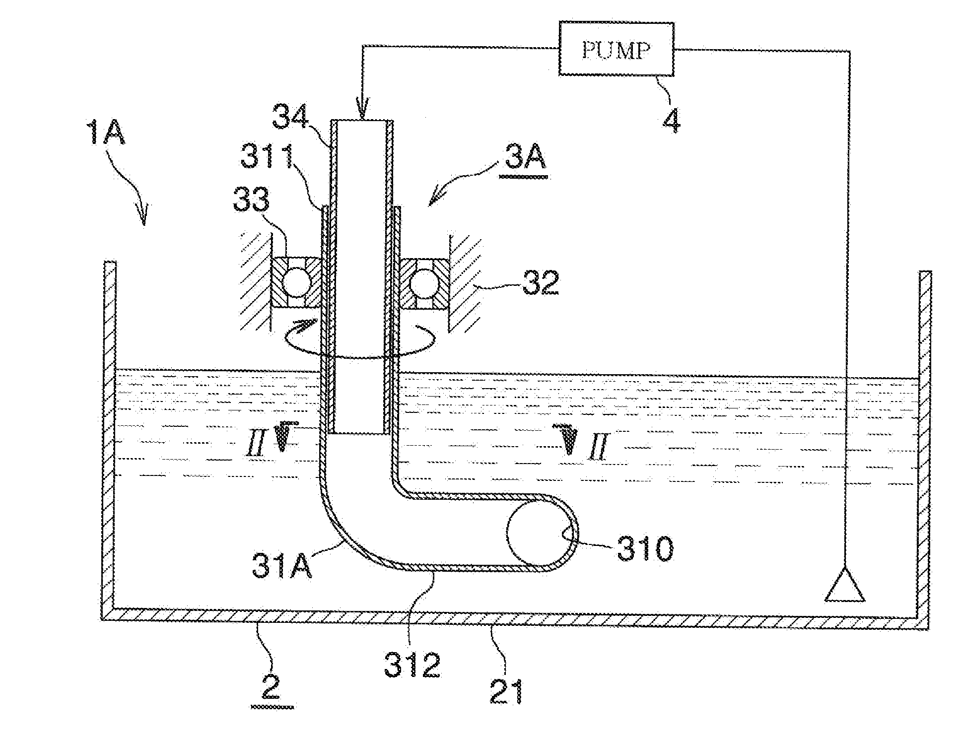
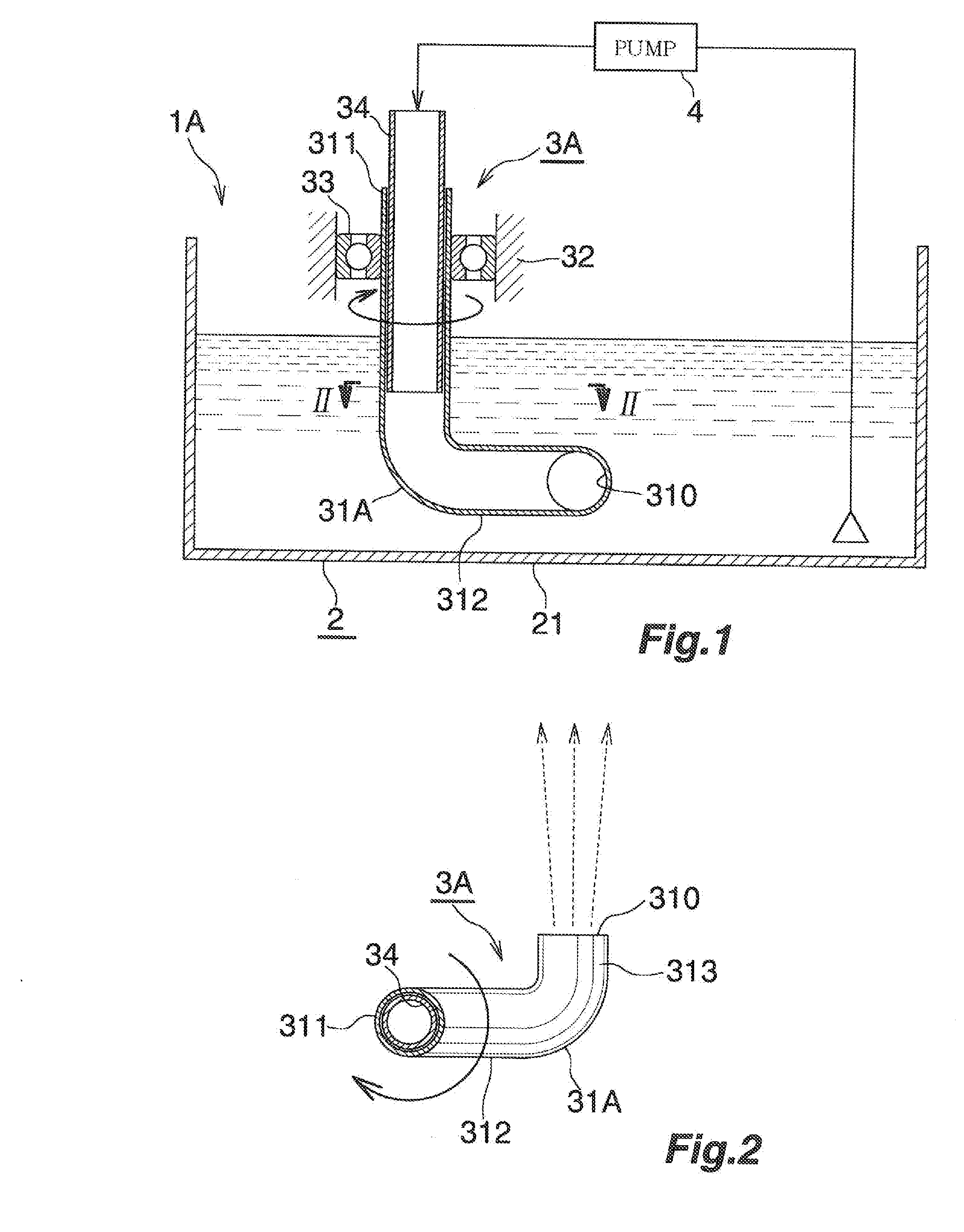
[0053]FIG. 1 and FIG. 2 illustrate a first embodiment of the invention.

[0054]A cutting fluid tank (1A) of the embodiment is provided with a tank body (2) and a fluid ejection apparatus (3A) installed in the tank body (2).

[0055]Although illustration is omitted, the tank body (2) is arranged below a work chamber of a machine tool, and cutting fluid containing chips and discharged from the work chamber flows therein from a predetermined inflow position (for example, a cutting fluid outlet of a chip conveyor) via the chip conveyor or a filter.

[0056]A cutting fluid supply pump configured to supply the cutting fluid toward the work chamber of the machine tool is provided in the interior of the tank body (2), and a chip separating apparatus composed of a centrifuge, a magnet separator, or the like is installed at a predetermined position (preferably, a position in proximity to the cutting fluid supply pump).

[0057]Within the tank body (2), the cutting fluid containing the chips forms a flow...

second embodiment

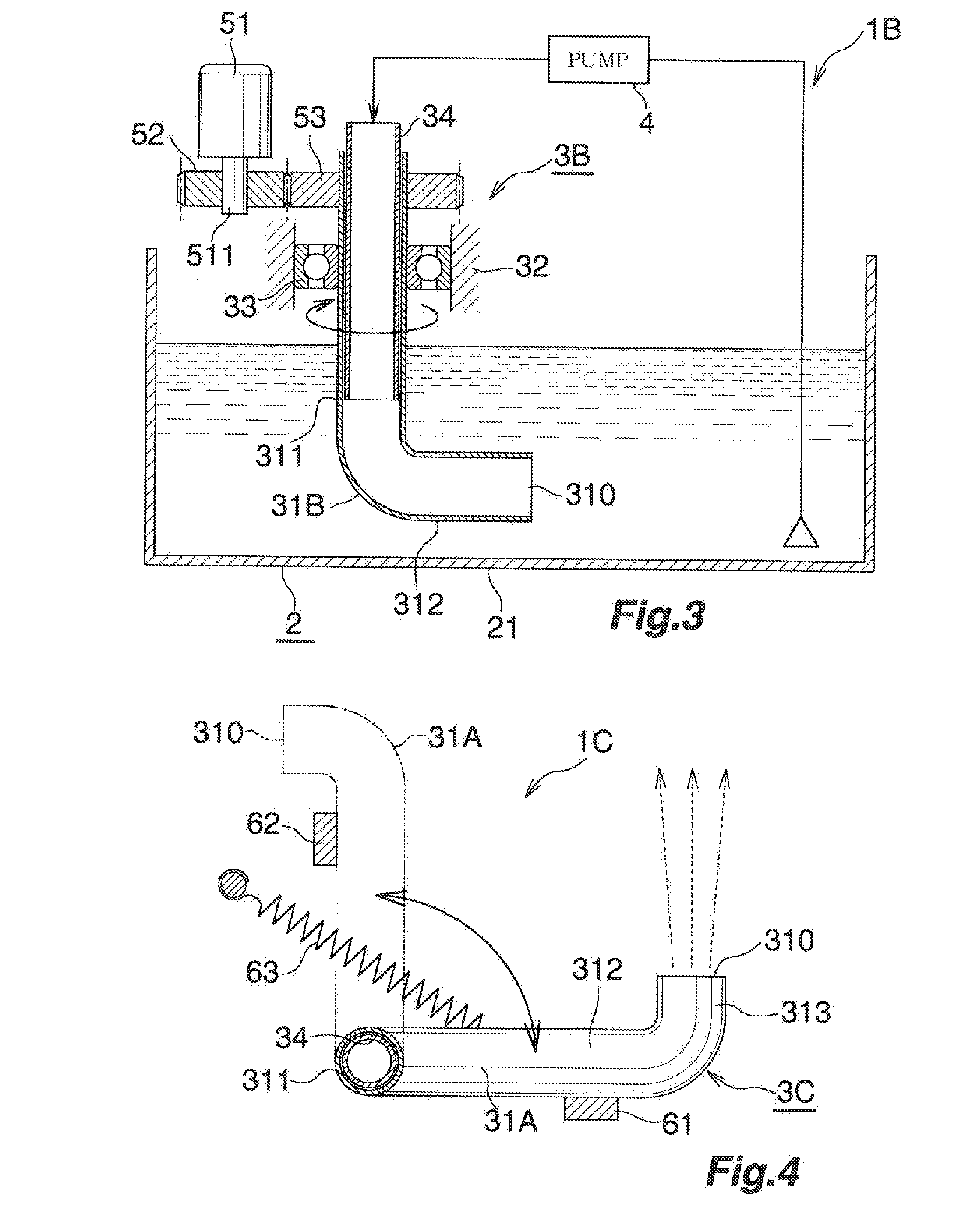
[0065]FIG. 3 is a drawing illustrating a second embodiment of the invention.

[0066]A cutting fluid tank (1B) of the second embodiment is substantially the same as the cutting fluid tank (1A) of the first embodiment illustrated in FIG. 1 and FIG. 2 except for the following point:

[0067]In the cutting fluid tank (1B) of the second embodiment, an ejection head (31B) of a fluid ejection apparatus (3B) does not have a bent end portion, and an ejection port (310) is defined by an opening at a distal end of a lower horizontal cylindrical portion (312). Therefore, the ejection port (310) faces a direction orthogonal to a vertical axis of rotation of the ejection head (31B).

[0068]The ejection head (31B) is configured to be rotationary driven by a motor (51). Specifically, rotation of an output shaft (511) of the motor (51) is transmitted to the ejection head (31B), via a drive wheel (52) mounted on an output shaft (511) of the motor (51), and a driven wheel (53) mounted on an upper end portion...

third embodiment

[0069]FIG. 4 is a drawing illustrating a third embodiment of the invention.

[0070]A cutting fluid tank (1C) of the third embodiment is substantially the same as the cutting fluid tank (1A) of the first embodiment illustrated in FIG. 1 and FIG. 2 except for the following point:

[0071]In the cutting fluid tank (1C) of the third embodiment, an ejection head (31A) of a fluid ejection apparatus (3C) is configured to be brought into reciprocatory pivotal motion within a predetermined pivotal angle. The ejection head (31A) is restrained in its pivotal angle to 90 degrees by two stoppers (61) and (62). The first stopper (61) is provided so as to come into contact with a side surface of a lower horizontal cylindrical portion (312) when the ejection head (31A) is at a pivotal position in which the ejection port (310) thereof is directed upward of FIG. 4 (the position indicated by a solid line in FIG. 4). The second stopper (62) is provided so as to come into contact with a side surface of the l...


PUM


Abstract

A cutting fluid tank includes: a fluid ejection apparatus configured to eject fluid toward cutting fluid containing chips and to be capable of varying at least one of a direction and a position of ejection with time in an interior of a tank body configured to store the cutting fluid containing the chips flowed from a work portion of a machine tool. The fluid ejection apparatus includes an ejection head having an ejection port rotatable about an axis of rotation. The ejection port is at a twisted position with respect to the axis of rotation, and the ejection head is rotated by a reaction force of the fluid ejected from the ejection port. Part of the cutting fluid stored in the cutting fluid tank is used as the fluid to be ejected from the ejection port.

Description

BACKGROUND OF THE INVENTION[0001]1. Field of the Invention[0002]The present invention relates to a cutting fluid tank used for a machine tool such as a machining center and a turning machine.[0003]2. Description of the Background Art[0004]For example, in a machine tool configured to perform a cutting work such as a machining center and a turning machine, cutting fluid is generally used for a purpose of lubrication and cooling of tools and discharge of chips.[0005]The cutting fluid discharged toward a work chamber of the machine tool by a cutting fluid supply pump is discharged to outside the work chamber together with chips scraped out from the work. The discharged cutting fluid flows into a tank body of a cutting fluid tank and stores temporarily after the chips mixed therein have been separated and removed by a chip conveyor or a filter, and is supplied therefrom to the work chamber again by the cutting fluid supply pump.[0006]However, the chips mixed in the cutting fluid cannot b...

Claims


Application Information

Patent Timeline
IPC IPC(8): B23Q11/00B23Q11/10
CPCB23Q11/1069B23Q11/0042B23Q11/1084B24B55/02Y10T137/85954B24B55/03Y10T137/86372B05B3/06B23B2250/12B23B27/10B23Q11/0057B01F25/21
Inventor MORIMURA, SHOICHI
Owner OKUMA CORP
Why Eureka
Try Eureka