Continuous Ore Process and Apparatus Using Plasma

a technology of continuous ore processing and plasma, which is applied in the direction of heat treatment apparatus, furnaces, charge manipulation, etc., can solve the problems of limited movement of torch, process lack of provision for optimizing ore processing reactor,

Inactive Publication Date: 2016-06-30
MILLS MICHAEL J +1
View PDF0 Cites 5 Cited by
  • Summary
  • Abstract
  • Description
  • Claims
  • Application Information

AI Technical Summary

Benefits of technology

[0012]The present invention provides an improvement to the conventional method of processing ores or metal complexes to extract metals by plasma arc processing. The improvement involves analysis of the ores and modeling of the reactor in order to select fluxes and / or reducing or oxidizing agents to the powdered ore before feeding the ore into the reactor. The method also involves control of the reaction during processing by indexing of the plasma torch or electrodes, and rapid cooling of the interior of the reactor to prevent escape of metal due to vaporization.
[0026]In order to increase cooling rate, the cooling system may include ducts or passages that are formed within the casing of the reactor, and extend through each of the casing sections. The use of a rapid cooling system in the casing of the reactor increases the temperature gradient as one moves away from the center-line of the plasma plume (which can reach temperatures of 10,000 Degrees Celsius), and helps ensures that vaporized metal is retained in the reactor and does not exit through the venting system. This adds to the metal recovery rate and improves efficiency.
[0027]The reactor is designed is such a way as to allow the tapping of liquid metal and slag at different heights. The feed rate and ore composition determine how often the reactor is tapped. After tapping, the reactor fills up again and the tapping process is repeated. When tapped the molten metal flows through a spout and into a ladle. The ladle is maneuvered into position that allows the ladle to pour the metal into anode molds, which are then placed into electro-refining cells (Moebius Cell) cells and electro-refined. This allows collection of the target metal.

Problems solved by technology

However, the process lacks provision for modeling the ore processing reactor to optimize selection of reagents, or for controlling the arc length during the reaction.
Also, while the plasma arc reactor disclosed in this patent includes a movable torch, movement of the torch is limited to a pivotal movement that does not permit height adjustment or indexing.

Method used


Image

  • Continuous Ore Process and Apparatus Using Plasma
  • Continuous Ore Process and Apparatus Using Plasma
  • Continuous Ore Process and Apparatus Using Plasma

Examples


Embodiment Construction

[0037]Throughout the following description and drawings, like reference numbers / characters refer to like elements. It should be understood that, although specific exemplary embodiments are discussed herein there is no intent to limit the scope of present invention to such embodiments. To the contrary, it should be understood that the exemplary embodiments discussed herein are for illustrative purposes, and that modified and alternative embodiments may be implemented without departing from the scope of the present invention.

[0038]In the following description, a preferred plasma arc reactor is described first, followed by a detailed description of an ore processing method that uses the preferred reactor, but that may also use plasma arc reactors other than the preferred reactor.

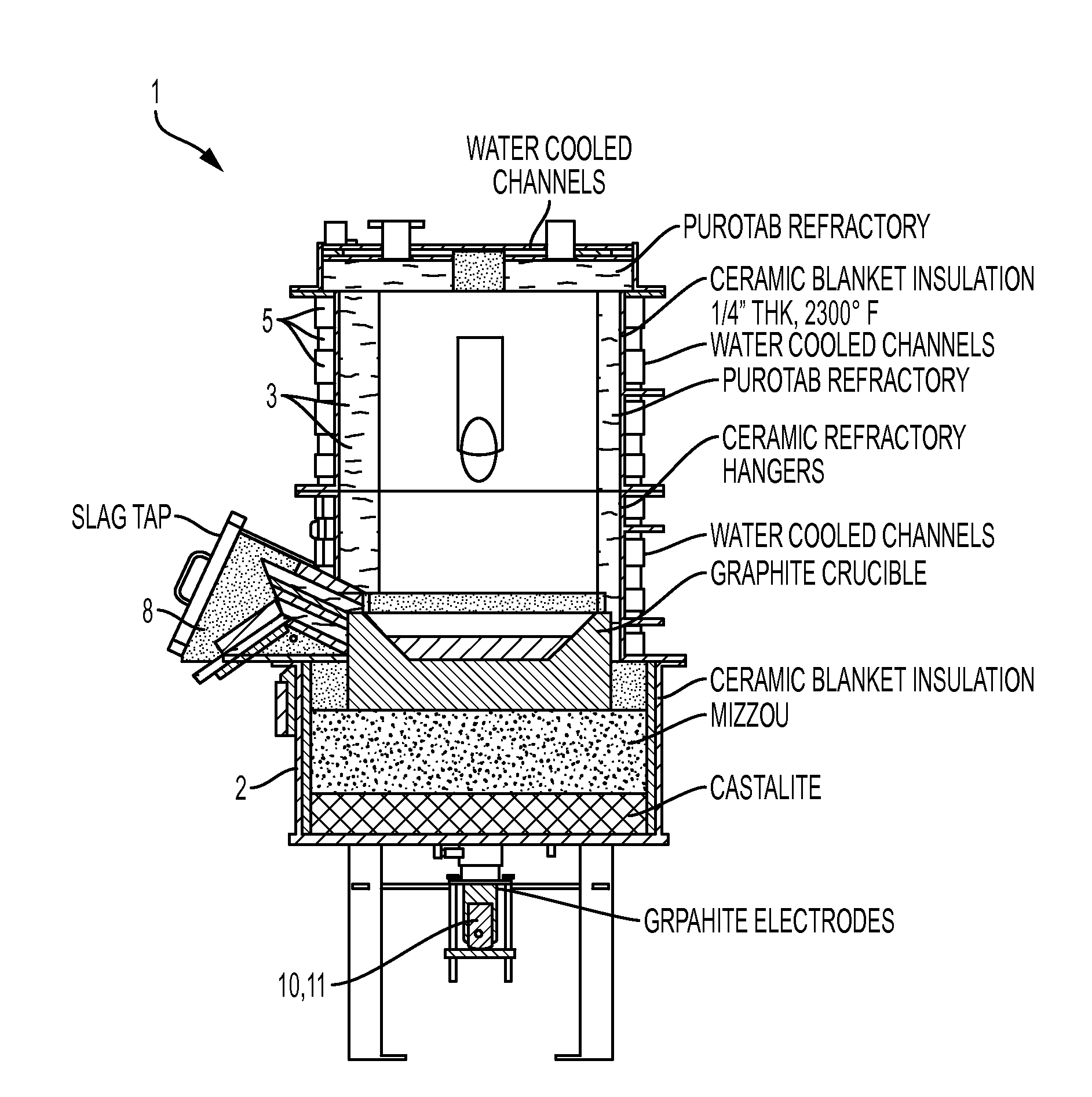
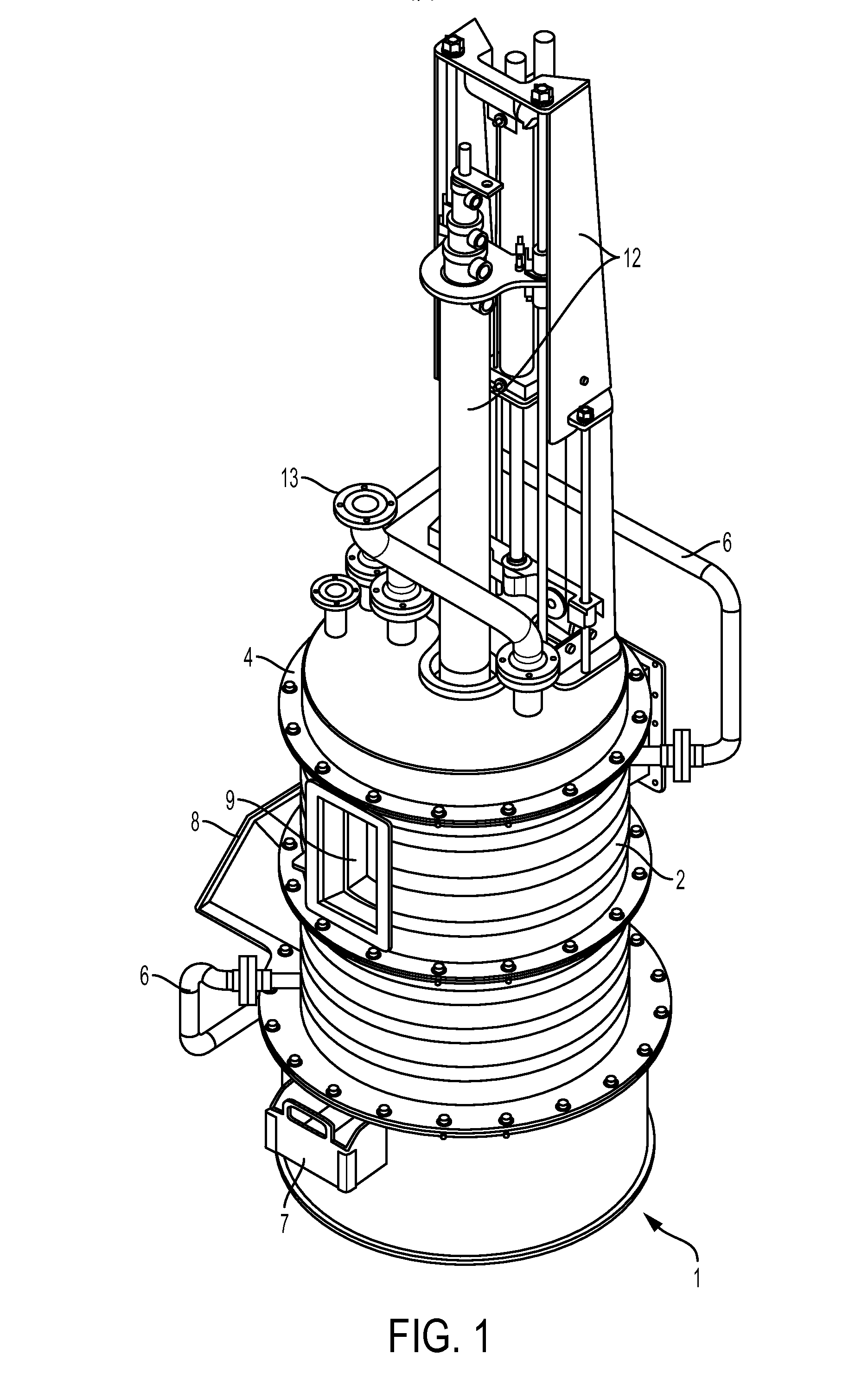
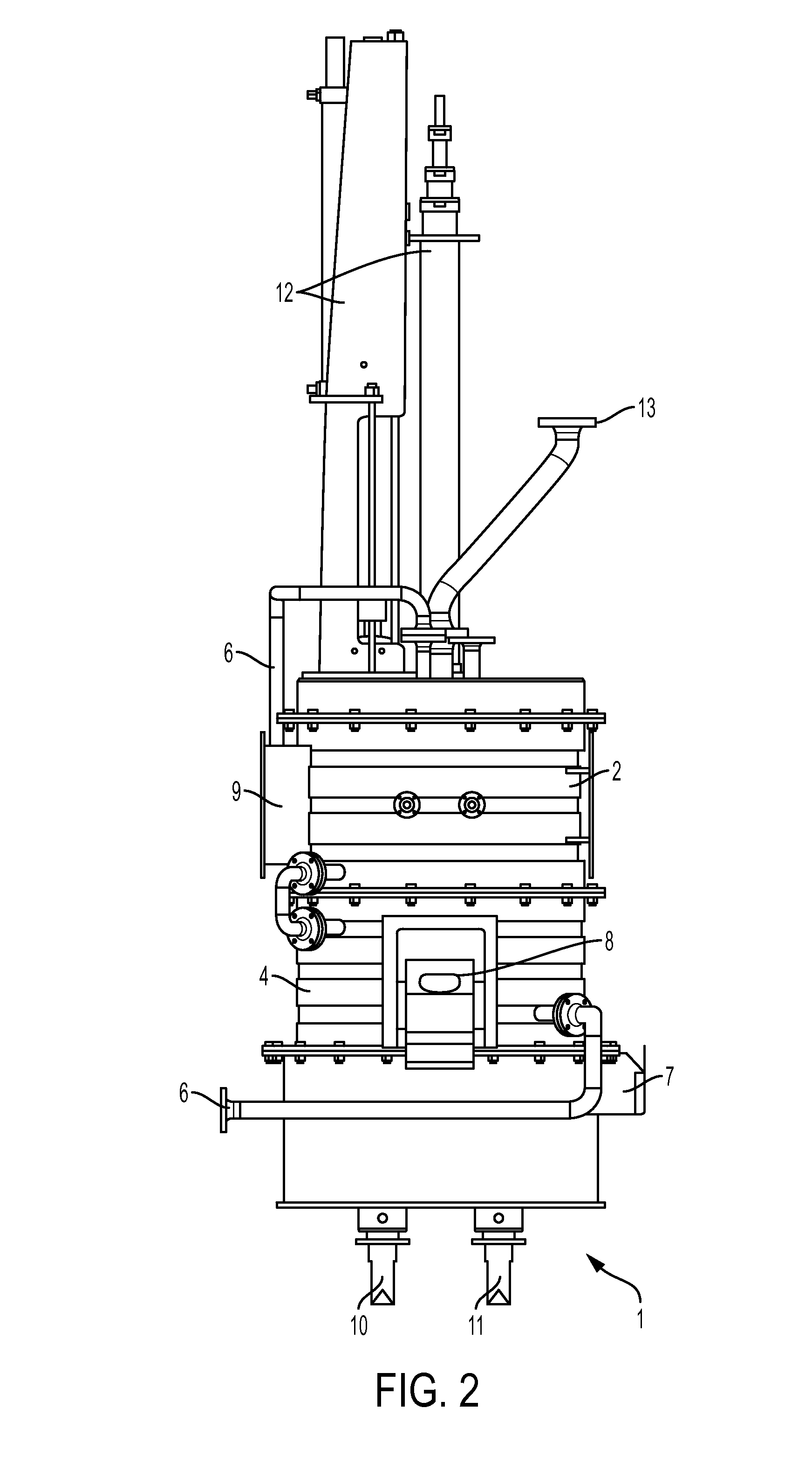
[0039]FIGS. 1-4 show an example of a plasma arc reactor 1 that may be used in the method of the invention. The reactor 1 includes a casing 2 having an inner refractory lining 3 and an outer shell 4 in which is ...


PUM

PropertyMeasurementUnit
thermal temperatureaaaaaaaaaa
poweraaaaaaaaaa
temperatureaaaaaaaaaa

Abstract

A method of processing ore using a plasma arc reactor includes the steps of first determining the content of the ore, modeling the plasma arc reaction for different stoichiometric ratios of ore to candidate reagents, selecting one or more of candidate reagents pre-mixing the selected reagents with the ore at corresponding stoichiometric ratios, and continuously feeding the pre-mixed ore into a plasma arc reactor, and controlling the plasma arc reaction according to the previously modeled conditions.

Description

[0001]This application claims the benefit of U.S. Provisional Patent Appl. Ser. No. 62 / 026,896, filed Jul. 21, 2014, and incorporated herein by reference.BACKGROUND OF THE INVENTION[0002]1. Field of the Invention[0003]The invention relates generally to a method for processing ore to recover precious and / or base metals, and to an ore processing reactor for use in the method.[0004]More specifically, the invention relates to improvements to a method of processing ore in a plasma arc reactor or furnace utilizing selected fluxes and / or reducing or oxidizing agents that have been pre-mixed with the ore, and to a continuous feed plasma arc reactor having height-indexed electrodes and integrated cooling ducts.[0005]2. Description of Related Art[0006]Traditional smelting processes use furnaces for melting ore to extract metals. In the case of an induction furnace, the thermal temperature can range from 2,000° F. to 6,000° F. Different fluxes and reducing agents are utilized in such processes...

Claims


Application Information

Patent Timeline
Patent Type & Authority Applications(United States)
IPC IPC(8): C22B11/02C22B4/00C22B4/08C22B9/14F27D3/08F27B1/08F27D3/00F27D9/00F27D11/10C22B9/10C21B11/10
CPCC22B11/02C22B9/103C22B4/005C22B4/08C22B9/14C21B11/10F27D2009/0035F27D3/0033F27D9/00F27D11/10F27D3/08F27D2009/0013F27B1/08C21B13/008C21B13/125
Inventor MILLS, MICHAEL J.KALNAS, DENNIS
Owner MILLS MICHAEL J
Why Eureka
Try Eureka