

Energy-storing-type high-pressure electric fuel pump, fuel-supplying apparatus, and application method therefor
a high-pressure electric fuel pump and energy-storing technology, applied in the direction of piston pumps, positive-displacement liquid engines, machines/engines, etc., can solve the problems of significant pressure variation, engine emissions of pollutants, unstable pressure in the fuel rail, etc., to increase the capacity of the fuel rail, reduce the fluctuation of pressure, simple, reliable and cheap
Active Publication Date: 2016-06-30
ZHEJIANG FAI ELECTRONICS
View PDF5 Cites 16 Cited by
- Summary
- Abstract
- Description
- Claims
- Application Information
AI Technical Summary
Benefits of technology
The invention aims to use an electrical device to release energy at specific phases, which improves the energy density in power drives and increases fuel pressure in pumps.
Problems solved by technology
1) Unstable pressure in the fuel rail before engine starts. When not used for a long time, the pressure will decrease to under 1 MPa, causing problems in engine start and the subsequent transition process, and also causing the engine to emit pollutants.
2) Unstable pressure in the fuel rail, and the pressure varies significantly with different phases of cams.
3) Complicated working conditions in transitioning from complete stoppage of fuel supply to resupplying fuels. It is hard to maintain the same rail pressure while the fuel stops or during engine idle.
4) When under partial loads, fuel is repeatedly heated. The low pressure metal matric diaphragm (MMD) is adversely impacted by dual effects of temperature and alternating pressure.
5) There is a strong link between the computational logic for the amount of fuel needed by engines and the regulation of the high-pressure pump. This results in complicated control logic.
6) If the fuel rail has a limited capacity, the pressure fluctuation would be increased.
If the fuel rail capacity is too large, a long process would be needed to establish the pressure before starting.
In sum, the above-described problems and dilemma exist in current GDI mechanic pumps.
However, it is difficult for current electronic fuel pumps to establish fuel pressure that is over 8 MPa.
However, the efficiency is much lower for a rotary motor driven one, and it costs more than a mechanic pump.
Current methods using linear motor to directly drive a plunger pump, instead of cams, result in low energy conversion efficiency and low time utilization efficiency.
To achieve high pressure using these methods, the products would become bulky and costly.
Method used
View moreImage
Smart ImageViewing Examples

Examples
first embodiment
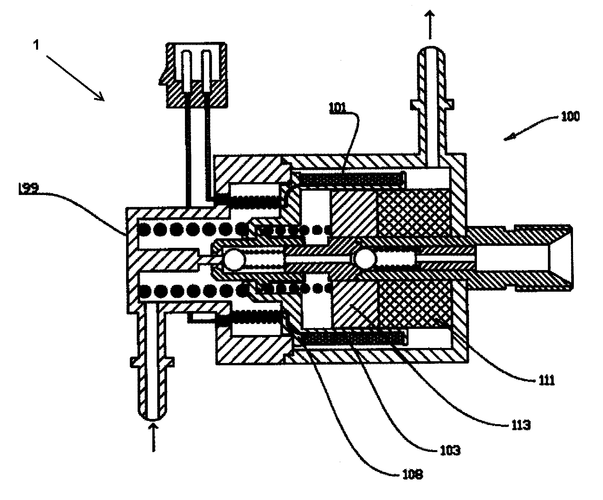
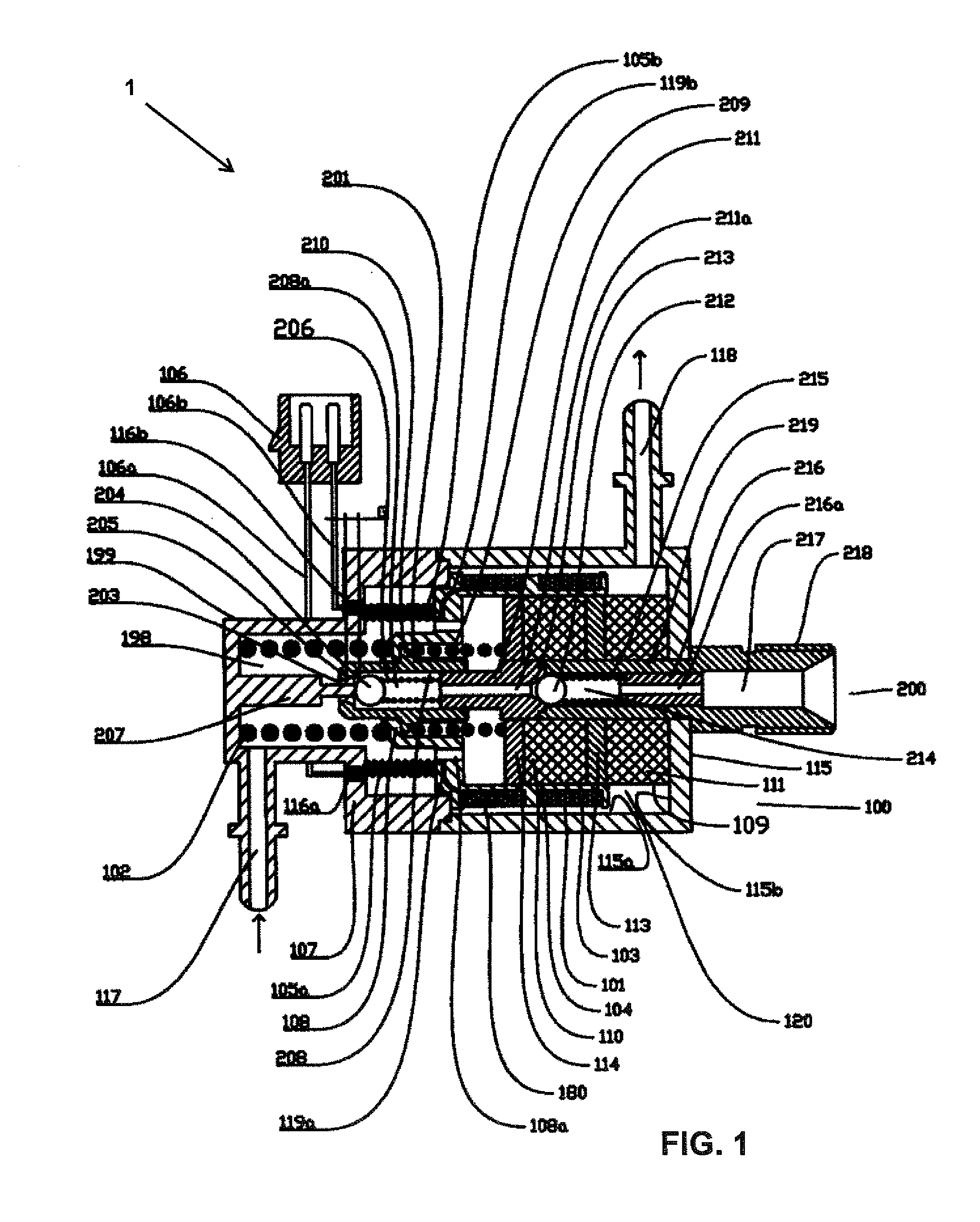
[0033]FIG. 1. The structure diagram of the energy-storing-type high pressure electronic fuel pump.
second embodiment
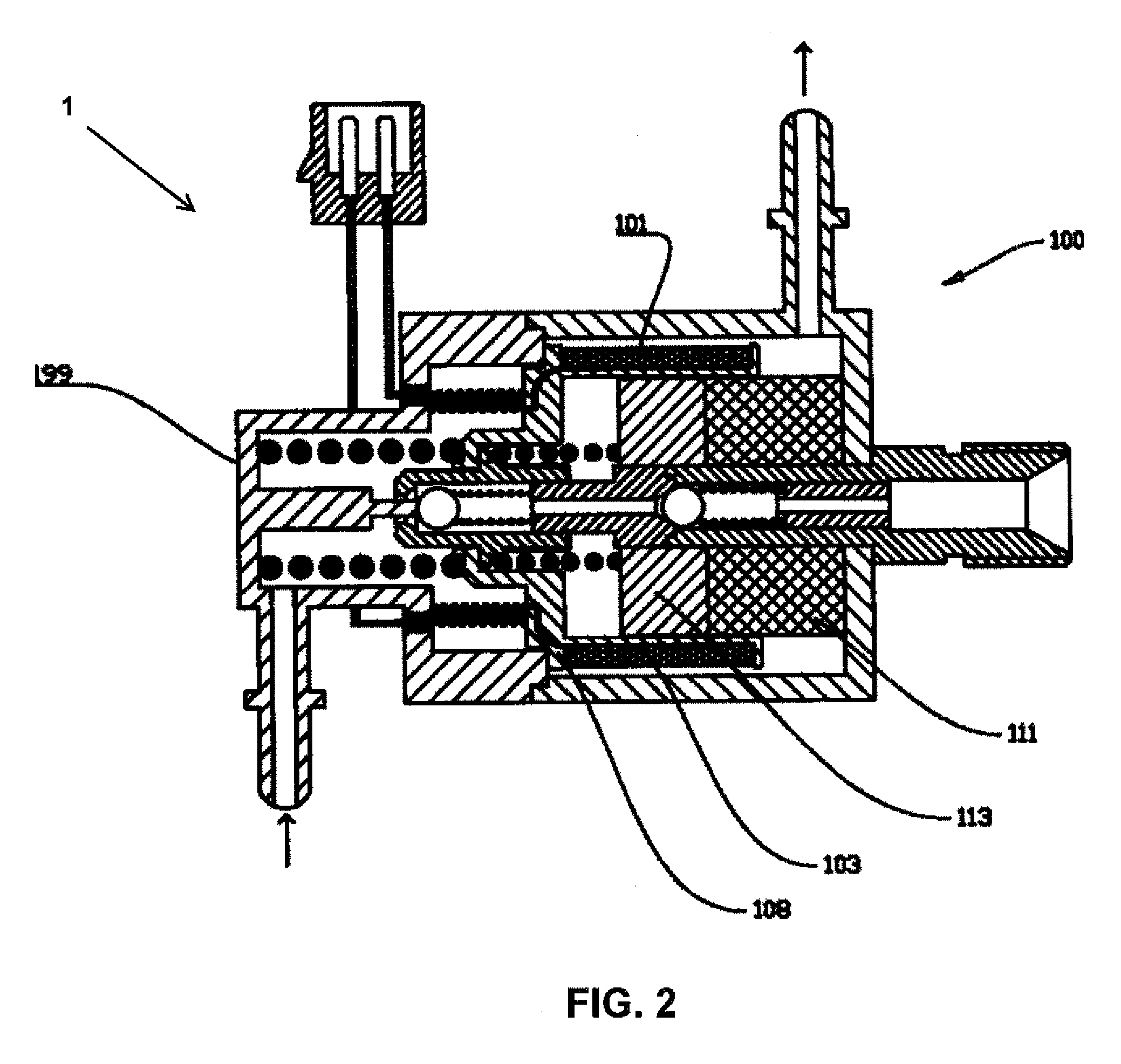
[0034]FIG. 2. The structure diagram of the energy-storing-type high pressure electronic fuel pump.
third embodiment
[0035]FIG. 3. The structure diagram of the energy-storing-type high pressure electronic fuel pump.
[0036]FIG. 3a. The structure diagram of the supplementary soft magnet of the third embodiment of the energy-storing-type high pressure electronic fuel pump.
[0037]FIG. 3b. The structure diagram of the basket of the third embodiment of the energy-storing-type high pressure electronic fuel pump.
[0038]FIG. 4. The structure diagram of the forth embodiment of the energy-storing-type high pressure electronic fuel pump.
Login to View More PUM
 Abstract
An energy-storing-type high-pressure electric fuel pump includes an electromagnetic driving apparatus and a plunger sleeve cylinder component. The plunger sleeve cylinder component includes a high-pressure volume, a plunger sleeve having a plunger hole, and a plunger capable of sliding within the plunger hole. A clearance volume of the plunger in the plunger hole is a high-pressure fuel chamber. A clearance volume between the electromagnetic driving apparatus and the plunger sleeve cylinder component forms a low-pressure fuel chamber. Under the action of the electromagnetic driving apparatus, the plunger sleeve cylinder component sucks a fuel in the low-pressure fuel chamber into the high-pressure fuel chamber and pressure-feeds the fuel into the high-pressure volume. The electromagnetic driving apparatus includes an energy storage apparatus, a movable part, and a still part.
Description
TECHNOLOGY FIELD[0001]This invention belongs to the field of engines technology, especially relating to the direct-injection spark-ignition system.BACKGROUND[0002]Direct injection technology is a way of directly injecting fuels into an engine with spark-ignition cylinders. Direct-injection engines have great fuel economy. They represent important development for future engines. The most important part for direct injection is the fuel-supplying system. A good fuel-supply system should satisfy as much as possible the combustion, performance and discharge requirements of the engines. The goal is to have direct injection engines that are affordable and easy to use.[0003]Gasoline Direct Injection (GDI) is used in an increasing number of car engines. Most of the direct-injection systems used in car engines are common-rail fuel line injection systems. Except during the start-up process, the pressure in the common-rail fuel lines typically remains between 8 and 20 MPa. Currently, the method...
Claims
Login to View More Application Information
Patent Timeline
 IPC IPC(8): F04B17/04F02M59/10F02M51/04
CPCF04B17/046F02M59/10F02M51/04F02M59/08
InventorXI, DAGUANGZHANG, PINGYANG, YANXIANGLIU, CHENGWEN
OwnerZHEJIANG FAI ELECTRONICS